A shock absorber for new energy vehicles
What is Al technical title?
Al technical title is built by PatSnap Al team. It summarizes the technical point description of the patent document.
A technology of new energy vehicles and shock absorbers, applied in the direction of shock absorbers, springs/shock absorbers, shock absorbers, etc., can solve the problems of elastic attenuation, unstable shock absorption effect, and reduce the service life of parts, and achieve Avoid elastic attenuation, good shock absorption effect, and improve the effect of the effect
Active Publication Date: 2020-03-27
NANTONG INST OF TECH
View PDF9 Cites 0 Cited by
Summary
Abstract
Description
Claims
Application Information
AI Technical Summary
This helps you quickly interpret patents by identifying the three key elements:
Problems solved by technology
Method used
Benefits of technology
Problems solved by technology
[0003] The purpose of the present invention is to provide a shock absorber for new energy vehicles in order to solve the above problems, which solves the problem that ordinary elastic shock absorbers will cause elastic attenuation during long-term use, and the shock absorption effect is unstable during use. The shock absorber will generate a lot of heat during use, which will reduce the service life of parts
Method used
Image
Click on the blue label to locate the original text in one second.
Reading with bidirectional positioning of images and text.
Examples
Embodiment Construction
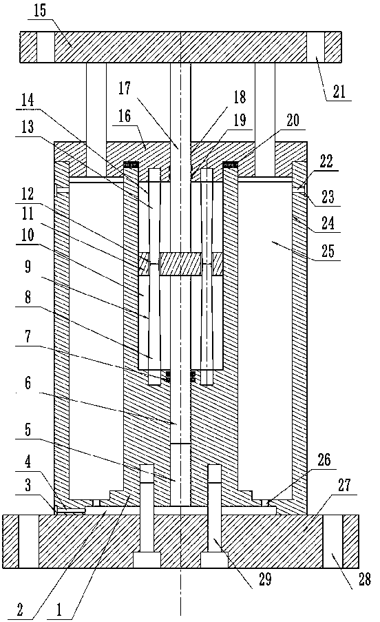
[0020] Such as figure 1 and figure 2 As shown, this specific embodiment adopts the following technical solutions: a shock absorber for new energy vehicles, including a housing 1, a groove 2, a filter screen-3, a breathing hole-4, a guide hole-5, and a guide post-6 , seal ring one 7, shaft body one 8, cone surface one 9, oil chamber 10, piston 11, communication hole 12, shaft body two 13, cone surface two 14, upper connecting seat 15, top cover 16, guide post two 17. Guide hole 2 18, sealing ring 2 19 and sealing gasket 20; the bottom surface of the housing 1 is provided with a groove 2 in the center; the left side of the groove 2 communicates with the outside air through the breathing hole 1 4; the breathing A filter screen-3 is provided in the opening on the left side of the hole-4; the guide hole-5 is located in the lower center of the housing 1, and the lower opening of the guide hole-5 communicates with the inside of the groove 2. The opening on the upper side of the gu...
PUM
Abstract
The invention discloses a damper used for a new energy automobile. The damper comprises a shell, a groove, a first filter net, a first breathing hole, a first guide hole, a first guide column, a firstseal ring, first shafts, first conical surfaces, an oil cavity, a piston, communicating holes, second shafts, second conical surfaces, an upper connecting base, a top cover, a second guide column, asecond guide hole, a second seal ring, a seal gasket and the like. The damper used for the new energy automobile is reasonable and simple in structure and low in production cost, damping is achieved under the double effects of a hydraulic mode and springs, the damping effect is good, and meanwhile, the phenomenon that a simplex elastic damping mode is adopted and causes elastic attenuation, and the damping effect is instable in use is also avoided; in addition, the phenomenon that a lot of heat is produced in the using process and the service lives of parts are shortened is avoided; and furthermore, the first conical surfaces are big-end-down conical surfaces, the second conical surfaces are big-end-up conical surfaces, accordingly, it is guaranteed that the larger the amplitude of the up-down movement of the piston, the larger the resistance of flowing of hydraulic oil, of the upper and lower sides of the piston, through the communicating holes, and therefore, the hydraulic damping effect is improved.
Description
technical field [0001] The invention relates to a shock absorber, in particular to a shock absorber for a new energy vehicle. Background technique [0002] New energy vehicles refer to the use of unconventional vehicle fuels as power sources (or the use of conventional vehicle fuels, the use of new vehicle power devices), integrated vehicle power control and advanced technology in driving, the formation of advanced technical principles, with Automobiles with new technologies and new structures; in order to quickly attenuate the vibration of the frame and body and improve the ride comfort and comfort of the car, the suspension system of the car is generally equipped with a shock absorber, and the two-way effect is widely used in the car. Barrel shock absorber; because the shock absorber is in a continuous compression and stretching process during work; ordinary elastic shock absorbers will cause elastic attenuation during long-term use, and the shock absorption effect is unst...
Claims
Application Information
Patent Timeline
Application Date:The date an application was filed.
Publication Date:The date a patent or application was officially published.
First Publication Date:The earliest publication date of a patent with the same application number.
Issue Date:Publication date of the patent grant document.
PCT Entry Date:The Entry date of PCT National Phase.
Estimated Expiry Date:The statutory expiry date of a patent right according to the Patent Law, and it is the longest term of protection that the patent right can achieve without the termination of the patent right due to other reasons(Term extension factor has been taken into account ).
Invalid Date:Actual expiry date is based on effective date or publication date of legal transaction data of invalid patent.