
End reinforcing structure of pulsed magnet coil

A technology of pulsed magnet and reinforcement structure, applied in the direction of coils, magnets, electromagnets, etc., can solve the problems of complex process, achieve the effect of simple manufacturing process, simple process, and improve the life of the magnet

Pending Publication Date: 2020-11-10
HUAZHONG UNIV OF SCI & TECH
View PDF0 Cites 1 Cited by
  • Summary
  • Abstract
  • Description
  • Claims
  • Application Information

AI Technical Summary

Problems solved by technology

[0005] Aiming at the above defects or improvement needs of the prior art, the present invention provides an end reinforcement structure of pulse magnet coils, the purpose of which is to solve the problem of using a large number of pre-stretched steel around the circumference of the magnet in the prior art. The technical problems caused by the complicated process caused by the pressure reinforcement of the magnet by the cable

Method used


Image

  • End reinforcing structure of pulsed magnet coil
  • End reinforcing structure of pulsed magnet coil
  • End reinforcing structure of pulsed magnet coil

Examples


Embodiment Construction

[0025] In order to make the object, technical solution and advantages of the present invention clearer, the present invention will be further described in detail below in conjunction with the accompanying drawings and embodiments. It should be understood that the specific embodiments described here are only used to explain the present invention, not to limit the present invention. In addition, the technical features involved in the various embodiments of the present invention described below can be combined with each other as long as they do not constitute a conflict with each other.

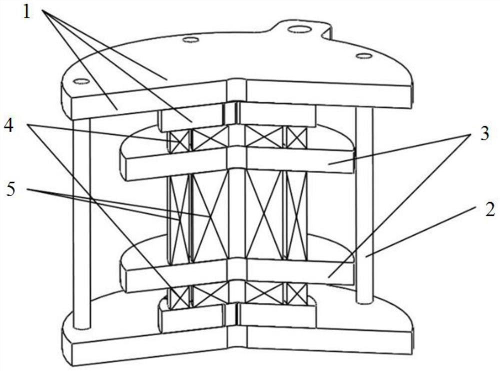
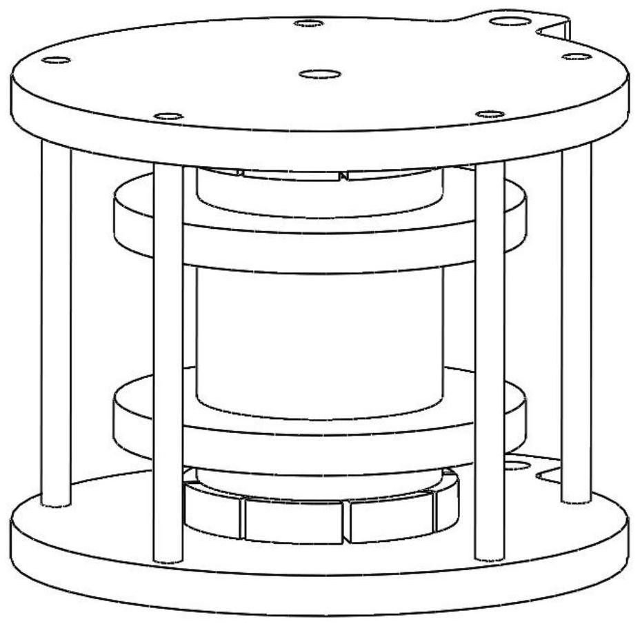
[0026] In order to achieve the above object, the present invention provides an end reinforcement structure of a pulse magnet coil, comprising: an external support assembly, a fixing assembly and an inner reinforcement plate;

[0027] Wherein, the external support component includes two parallel end surfaces, which are respectively fixedly placed at both ends of the pulse magnet coil, and paralle...


PUM


Abstract

The invention discloses an end reinforcing structure of a pulse magnet coil. The end reinforcing structure comprises an external supporting assembly, a fixed assembly and an inner-layer reinforcing plate, wherein the external supporting assembly comprises two parallel end faces which are fixedly placed at the two ends of the pulse magnet coil respectively and are parallel to the plane of the pulsemagnet coil; the fixed assembly is fixedly placed between the two end faces of the external supporting assembly and is perpendicular to the end faces of the external supporting assembly, and the connecting point is located at the edge of the end face of the external supporting assembly. The number of the inner-layer reinforcing plates is an even number, and the inner-layer reinforcing plates arearranged in the pulse magnet coil, divide the pulse magnet coil into a plurality of sections of relatively independent coils in the axial direction and are used for reducing the maximum deformation quantity of the pulse magnet coil by enabling the end part areas of all the sections of coils to deform respectively in the discharging process of the pulse magnet coil; the end reinforcing structure isfew in accessories and simple in structure, and the effect of prolonging the service life of the magnet can be achieved through a simple process.

Description

technical field [0001] The invention belongs to the technical field of strong magnetic field reinforcement, and more particularly relates to an end reinforcement structure of a pulse magnet coil. Background technique [0002] As an extreme research condition of modern science, a strong magnetic field provides better opportunities and broader prospects for the opening up of new fields, the discovery of new theories and the proposal of new ideas. In the past 30 years, with the research and development of high-strength, low-resistivity alloy wires and high-performance interlayer reinforcement fibers, the pulsed strong magnetic field has developed from the experimental exploration of about 70T to the realization of 100T ultra-high pulsed magnetic field. [0003] Pulse magnets are important equipment for generating high-intensity magnetic fields. At present, all pulse magnet devices that generate ultra-high-intensity magnetic fields at home and abroad use pulse magnets. For exam...

Claims


Application Information

Patent Timeline
Patent Type & Authority Applications(China)
IPC IPC(8): H01F7/20H01F5/00
CPCH01F5/00H01F7/202
Inventor 彭涛李奕衡李亮尚会东江山
Owner HUAZHONG UNIV OF SCI & TECH
Features
  • Generate Ideas
  • Intellectual Property
  • Life Sciences
  • Materials
  • Tech Scout
  • Unparalleled Data Quality
  • Higher Quality Content
  • 60% Fewer Hallucinations
Learn More