A battery protection device

A battery protection device, battery cell technology, applied in secondary batteries, battery pack components, circuits, etc., can solve the problems of no automatic adjustment, inability to match different temperatures of batteries, affecting battery life, etc., to ensure safety and reliability. The effect of stability

Active Publication Date: 2022-07-26
ANHUI ZHENGXIBIAOWANG NEW ENERGY CO LTD
View PDF11 Cites 0 Cited by
  • Summary
  • Abstract
  • Description
  • Claims
  • Application Information

AI Technical Summary

Problems solved by technology

[0002] As batteries are used more and more widely, battery safety issues are becoming more and more prominent. The battery will generate a lot of heat when it supplies power, so it is necessary to effectively cool the battery. In case of external short circuit or other accidents, the impact of high current will cause overheating, which may even cause the battery to burn and explode. Heat dissipation will not only affect the life of the battery, but also increase the instability of the battery and pose a safety hazard. In the prior art, the battery is generally cooled by continuously feeding cold air or blowing air into the battery box. However, a On the one hand, it does not have the function of automatic adjustment with the change of battery temperature, so it cannot match the different temperatures of the battery in real-time use to maintain the ideal state of battery use, especially when the battery temperature rises abnormally and rapidly, it is difficult to adjust heat dissipation in time to ensure The safety and stability of the battery. On the other hand, when the battery burns or even explodes in an accident, the cooling air introduced at this time will help the combustion to a certain extent. As a result, the battery is very easy to burn violently, and then more serious secondary accidents occur, and the safety is poor

Method used


Image

  • A battery protection device
  • A battery protection device
  • A battery protection device

Examples


Embodiment Construction

[0031] In order to make the objectives, technical solutions and advantages of the present disclosure clearer, the present disclosure will be further described in detail below with reference to specific embodiments.

[0032] It should be noted that, unless otherwise defined, the technical or scientific terms used in one or more embodiments of the present specification shall have the usual meanings understood by those with ordinary skill in the art to which this disclosure belongs. The terms "first," "second," and similar terms used in one or more embodiments of this specification do not denote any order, quantity, or importance, but are merely used to distinguish the various components. "Comprises" or "comprising" and similar words mean that the elements or things appearing before the word encompass the elements or things recited after the word and their equivalents, but do not exclude other elements or things. Words like "connected" or "connected" are not limited to physical o...


PUM


Abstract

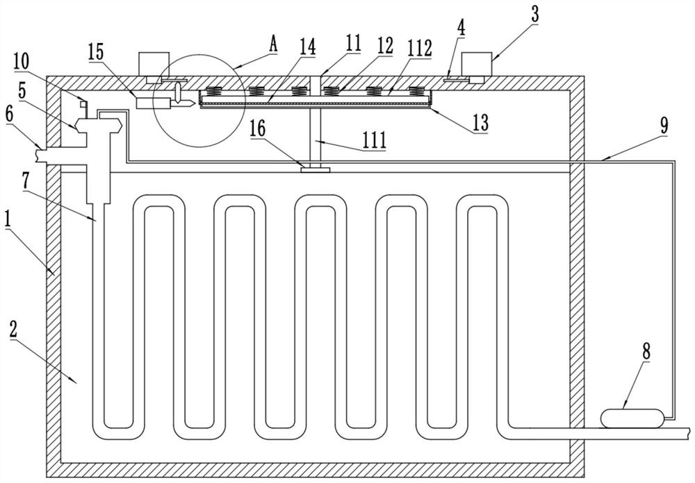
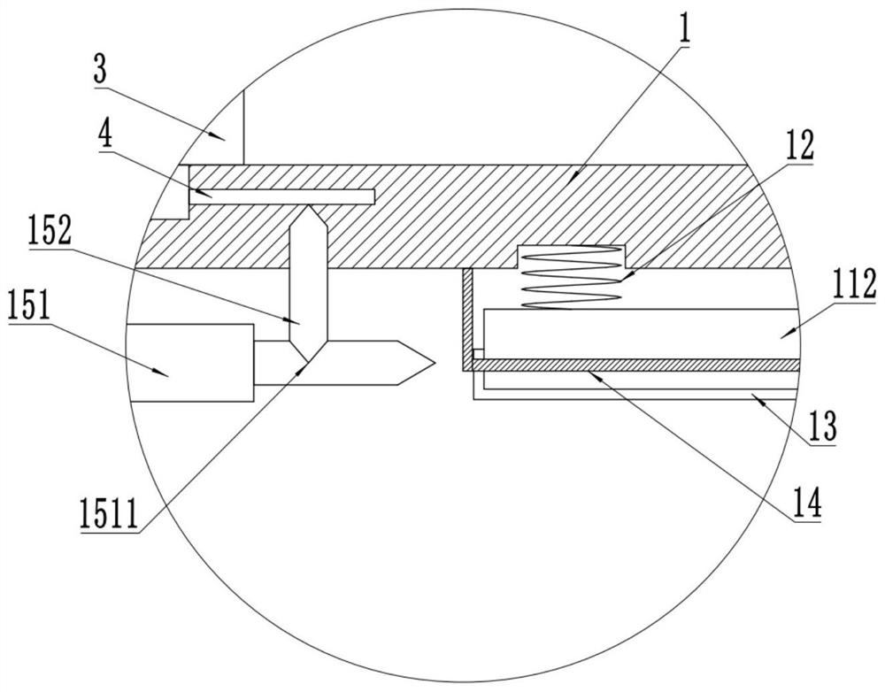
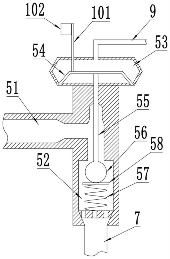
One or more embodiments of this specification provide a battery protection device, which includes a battery case, and the poles at both ends of the battery case are electrically connected with connecting pieces to connect and conduct with the tabs of the battery core body, and are externally connected through an expansion valve. There is a liquid inlet pipe to introduce the cooling liquid, and it is attached to the outer side wall of the battery core through the liquid outlet pipe to cool down and dissipate heat. The temperature sensing package is filled with expansion liquid to sense the temperature of the liquid pipe and control the expansion. The opening and closing degree of the valve can automatically adjust the heat dissipation in real time. There is also a switch mechanism on the expansion valve. At the same time, a screw and a nut that engage with each other are provided. The hollow interior of the nut is filled with flame retardant powder. The elastic film is clamped and fixed by the elastic rope. When the sensing temperature of the temperature sensor reaches the limit threshold, the switch mechanism can be triggered to trigger the conduction top thorn mechanism to pierce the connecting piece and the elastic rope to throw the flame retardant powder, thereby realizing the functions of timely extinguishing and isolating the battery.

Description

technical field [0001] One or more embodiments of this specification relate to the technical field of batteries, and in particular, to a battery protection device. Background technique [0002] As batteries are used more and more widely, battery safety issues are becoming increasingly prominent. Batteries generate a lot of heat when supplying power. Therefore, it is necessary to effectively cool the batteries. In unexpected situations such as external short circuit, the impact of large current will cause overheating, and even cause the battery to burn and explode. At the same time, when the battery is in the state of overcharge and overdischarge, due to the increase of current, the temperature will also rise rapidly. Heat dissipation will not only affect the life of the battery, but also increase the instability of the battery, which is a potential safety hazard. In the prior art, the battery is generally cooled by continuously introducing cold air or blowing air into the ba...

Claims


Application Information

Patent Timeline
Patent Type & Authority Patents(China)
IPC IPC(8): H01M50/244H01M10/613H01M10/635H01M10/6551H01M10/6568A62C3/16
CPCH01M10/613H01M10/6568H01M10/635H01M10/6551A62C3/16Y02E60/10
Inventor 曹然超王素侠曹劲梵
Owner ANHUI ZHENGXIBIAOWANG NEW ENERGY CO LTD
Why Eureka
Try Eureka