Surface cleaning device for metal recovery

A surface cleaning and metal technology, which is applied in the direction of using tools, cleaning methods and utensils, chemical instruments and methods, etc., can solve the problems of large impurities and difficult to clean, and the influence of metal rod cleaning, etc. The effect of high squeezing force

Inactive Publication Date: 2020-11-13
邱洁
View PDF1 Cites 0 Cited by
  • Summary
  • Abstract
  • Description
  • Claims
  • Application Information

AI Technical Summary

Problems solved by technology

A metal rod surface cleaning device in the above-mentioned patent has the following disadvantages: when the existing device cleans the surface of the metal rod, it may not be easy to clean due to the large volume of impurities adhered to the surface of the metal rod, thereby damaging the metal rod. Cleaning of rods affects

Method used


Image

  • Surface cleaning device for metal recovery
  • Surface cleaning device for metal recovery
  • Surface cleaning device for metal recovery

Examples


Embodiment 1

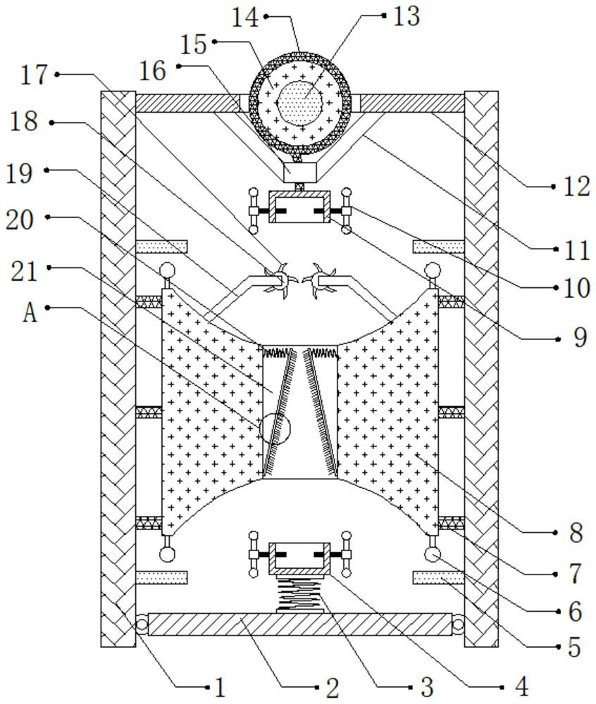
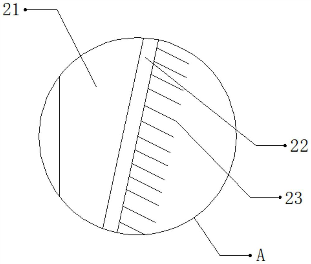
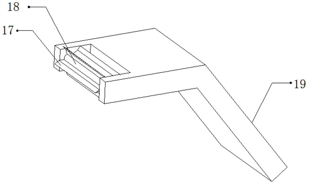
[0027] refer to Figure 1-3 , a surface cleaning device for metal recovery, comprising two fixed plates 1, the outer walls of the opposite sides of the two fixed plates 1 are connected with iron cables 7 by bolts, and the outer walls of one side of the iron cables 7 are connected with cleaning plates 8 by bolts, The top outer wall of cleaning plate 8 is provided with cleaning port 21, and the bottom inner wall of cleaning port 21 is connected with cleaning brush 22 by hinge, and cleaning brush 22 is funnel-shaped distribution, and one side outer wall of cleaning brush 22 is provided with a plurality of barbs 23, The opposite side outer walls of the two fixed plates 1 are all connected with two fixed blocks 5 by bolts, and the both sides of the top outer wall of the cleaning plate 8 and the both sides of the bottom outer wall are all connected with spheres 6 by bolts, and the spheroids 6 and the fixed blocks 5 Correspondingly, the position of the outer walls on the opposite sid...

Embodiment 2

[0036] refer to Figure 4 , a surface cleaning device for metal recovery. Compared with Embodiment 1, the outer walls of one side of the two fixed plates 1 are connected with a vibration motor 24 by bolts. When the metal rod is cleaned, the vibration motor 24 is started. , so as to deal with the impurities adhered inside the device by vibration, so as to clean the device.

[0037]Working principle: when in use, place the metal rod to be cleaned on the device, fix the bottom of the metal rod to the inside of the first fixed sleeve 4, and fix the top of the metal rod to the inside of the second fixed sleeve 9 through the cleaning port 21 Inside, twist the fastening bolt 10 to fix the two ends of the metal pipe through the fastening bolt 10. After the fixing is completed, start the motor, and the motor will drive the winding roller 15 to rotate, so as to wind the pull cord 14 , so as to drive the metal rod to reciprocate up and down, thereby cleaning the surface of the metal rod...


PUM


Abstract

The invention discloses a surface cleaning device for metal recovery. The device comprises two fixing plates, the outer walls of the opposite sides of the two fixing plates are fixedly connected withiron chains, the outer walls of one sides of the iron chains are fixedly connected with cleaning plates, the outer wall of the top of each cleaning plate is provided with a cleaning opening, the innerwall of the bottom of each cleaning opening is connected with a cleaning brush through a hinge, and the cleaning brushes are distributed in a funnel shape. A plurality of barbs are arranged on the outer wall of one side of each cleaning brush, the outer walls of the opposite sides of the two fixing plates are each fixedly connected with two fixing blocks, and the two sides of the outer walls of the tops and the two sides of the outer walls of the bottoms of the cleaning plates are fixedly connected with balls. The interference caused to cleaning of a metal rod by the fact that large impurities are bonded to the surface of the metal rod can be prevented, the influence caused on the cleaning of the metal rod by the fact that stubborn impurities are bonded to the surface of the metal rod andare not easy to remove can be prevented, and the metal rod can be effectively cleaned according to the size of the metal rod.

Description

technical field [0001] The invention relates to the technical field of metal recovery, in particular to a surface cleaning device for metal recovery. Background technique [0002] When metal is recycled, the surface of the metal is usually cleaned by a cleaning device. [0003] After searching, the Chinese patent authorization number is CN104624535B, which discloses a metal rod surface cleaning device. The metal rod surface cleaning device includes a frame on which a rotating drum with a cleaning inner cavity is rotatably connected. One end of the rotating drum has an inlet for the metal rod to enter the cleaning inner cavity, and the other end of the rotating drum has an inlet for the cleaning inner cavity. The metal rod passes through the outlet of the cleaning inner cavity, and an accommodation space for accommodating the friction medium is formed between the inner wall of the cleaning inner cavity and the outer wall of the metal rod pierced in the cleaning inner cavity....

Claims


Application Information

Patent Timeline
Patent Type & Authority Applications(China)
IPC IPC(8): B08B1/02B08B7/02B08B13/00B08B1/20
CPCB08B7/02B08B13/00B08B1/12B08B1/20B08B1/165
Inventor 邱洁
Owner 邱洁
Why Eureka
Try Eureka