Rolling shaft type pay-off device and pay-off method

A wire pay-off device and roller technology are applied in the directions of transportation and packaging, transportation of filamentous materials, cable laying equipment, etc., which can solve the problems of poor safety, inability to use, and high cost of crane pay-off, and prevent shaking and deviation. Easy installation and stable operation

Inactive Publication Date: 2020-11-13
国网山东省电力公司高密市供电公司 +1
View PDF7 Cites 0 Cited by
  • Summary
  • Abstract
  • Description
  • Claims
  • Application Information

AI Technical Summary

Problems solved by technology

These two pay-off methods cannot be used when encountering larger pay-off rollers
Larger pay-off rollers usually use a crane to lift the pay-off roller for pay-off, which is expensive and less safe to use a crane to pay-off

Method used


Image

  • Rolling shaft type pay-off device and pay-off method

Examples


specific Embodiment approach 1

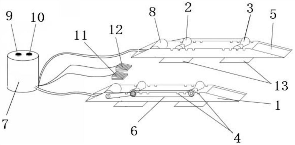
[0028] like figure 1 As shown, the present invention provides a roller type pay-off device, which mainly includes two bases 1 arranged at intervals on the left and right, and the distance between the two bases 1 is adjustable, and the base 1 is provided with a distance adjusting structure. The front roller 3 and the rear roller 2 are rotatably installed on the adjustment structure, and the front roller 3 and the rear roller 2 are arranged at intervals. Positioning structure, the front roller 3 and the rear roller 2 on the two bases 1 are driven by the drive unit to rotate synchronously; the front part of the base 1 is provided with an inclined running part 5, so as to facilitate the rolling of the pay-off roller through the running part 5 On the front roller 3 and the rear roller 2 on the upper part of the base 1, two independent bases 1 are provided and the distance between them is adjustable to adapt to pay-off rollers of different widths; by setting the distance adjustment ...

specific Embodiment approach 2

[0033] The present invention also provides a pay-off method for using the above-mentioned pay-off device, which mainly includes the following steps:

[0034] A1: Adjust the distance between the two bases 1 by moving the base 1 to adapt to the width of the pay-off roller;

[0035] A2: Select two adjustment grooves 4 with suitable spacing to install the front roller 3 and the rear roller 2 in them;

[0036] A3: Select a suitable first chain 6 to drive the front roller 3 and the rear roller 2 to connect;

[0037] A4: Manually roll the pay-off roller from the slope at the front of the base 1 to the front roller 3 and the rear roller 2 located on the upper part of the base 1 and support it on the positioning structure;

[0038] A5: Complete the pay-off operation by manually rotating the pay-off roller; or, drive the second chain and the first chain 6 to rotate through the DC motor 8 and then drive the front roller 3 and the rear roller 2 to rotate synchronously to realize the rota...


PUM


Abstract

The invention provides a rolling shaft type pay-off device and a pay-off method. According to the scheme, the rolling shaft type pay-off device comprises two bases which are arranged left and right atan interval, the distance between the two bases is adjustable, a distance adjusting structure is arranged on the bases, front rolling shafts and rear rolling shafts are rotatably mounted on the distance adjusting structure, the front rolling shafts and the rear rolling shafts are arranged at intervals, positioning structures used for positioning pay-off rollers are arranged on the front rolling shafts and the rear rolling shafts, and the front rolling shafts and the rear rolling shafts on the two bases are driven by a driving unit to rotate synchronously; and inclined walking parts are arranged at the front parts of the bases, so that the pay-off rollers can conveniently roll to the front rolling shafts and the rear rolling shafts at the upper parts of the bases through the walking parts.The rolling shaft type pay-off device is suitable for automatic pay-off of various pay-off rollers, particularly large pay-off rollers, and can be mounted without auxiliary equipment such as a crane.

Description

technical field [0001] The invention relates to the field of cable equipment, in particular to a roller type wire pay-off device and a wire pay-off method. Background technique [0002] The pay-off device is a common pay-off auxiliary tool in line construction. The main function is to make the pay-off roller easy to rotate through mechanical means, so as to achieve the purpose of pay-off. [0003] There are two types of pay-off vehicles currently in use: one is to use an iron rod to pass through the middle of the pay-off roller, and then use an angle grinder to raise the two ends of the iron rod so that the pay-off roller is off the ground for easy rotation. The first type of pay-off device has a large volume, long installation time, and the pay-off roller is easy to deviate when it rotates; the other is a tray type pay-off device. The base of this device has two layers. When paying off, put the pay-off roller on On the turntable, the pay-off is completed by turning. This ...

Claims


Application Information

Patent Timeline
Patent Type & Authority Applications(China)
IPC IPC(8): B65H49/24H02G1/06
CPCB65H49/24H02G1/06B65H2701/34
Inventor 刘超冯子刚王青迟甜甜杜德琪姜艳光马宝坤李帅华高燕建袁学志
Owner 国网山东省电力公司高密市供电公司
Why Eureka
Try Eureka