Supercharge Your Innovation With Domain-Expert AI Agents!

Double-flap jacking type sucker rod workover operation power slip and operation process

A technology for power slips and sucker rods, which is applied to drill pipes, drilling equipment, earth-moving drilling, etc., can solve the problems of high labor occupation, high labor intensity, and high safety risks, and achieve the effect of improving efficiency and realizing automation.

Active Publication Date: 2020-11-13
SLOF KANGBEI IND & TRADING
View PDF3 Cites 11 Cited by
  • Summary
  • Abstract
  • Description
  • Claims
  • Application Information

AI Technical Summary

Problems solved by technology

[0002] The traditional workover operation method is mainly manual. After the sucker rod needs to be manually straightened, the sucker rod slips are clamped, rotated and locked to support the entire operation, and as the sucker rod is lifted by the workover hook, The entire sucker rod operation has been completed, and there are problems such as high labor occupation, high labor intensity, poor outdoor construction environment, and high safety risks, especially the sucker rod operation is more prominent

Method used


Image

  • Double-flap jacking type sucker rod workover operation power slip and operation process
  • Double-flap jacking type sucker rod workover operation power slip and operation process
  • Double-flap jacking type sucker rod workover operation power slip and operation process

Examples


Embodiment 1

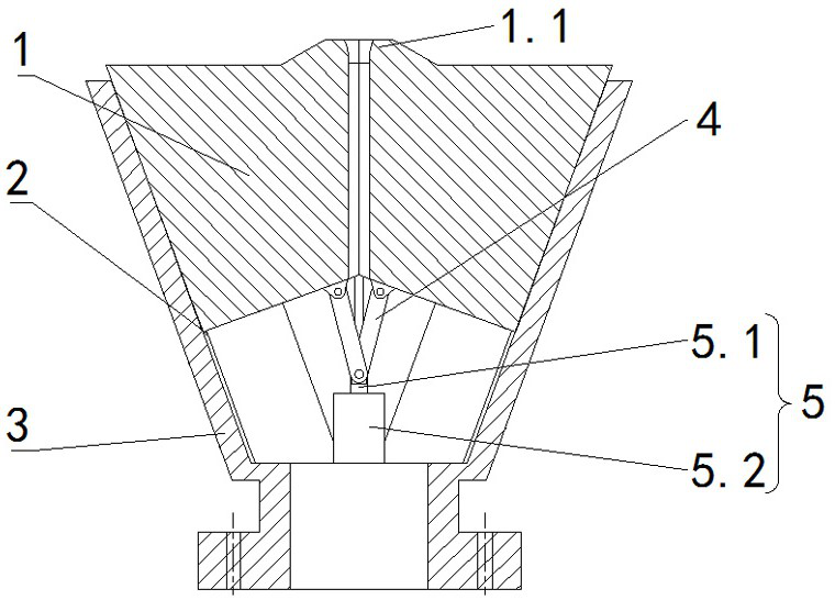
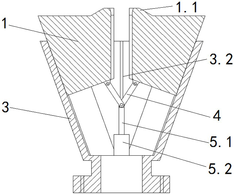
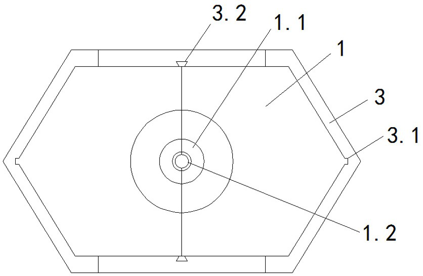
[0025] Embodiment 1, with reference to figure 1 with 2 , a double-lobe jacking type sucker rod workover operation power slip mentioned in the present invention, including a sucker rod holding unit 1, a follow-up sealing device 2, a power slip box 3, a connecting rod 4, and a hydraulic cylinder 5. The double-lobe jacking type sucker rod workover power slips are integrally installed on the small cross 7, and the elevator 6 is installed on the top of the double-lobe jacking type sucker rod workover power slips. The slip box 3 is installed with the hydraulic cylinder 5, the connecting rod 4, and the sucker rod support unit 1 sequentially from bottom to top, and the hydraulic cylinder 5 is divided into two groups and located at the front and rear symmetrical positions inside the power slip box 3. The cylinder 5 includes a hydraulic cylinder piston 5.1 and a hydraulic cylinder body 5.2. The upper ends of the hydraulic cylinder piston 5.1 are respectively connected to the bottoms of...

Embodiment 2

[0038] Embodiment 2, a double-lobe jacking type sucker rod workover operation power slip mentioned in the present invention, including a sucker rod holding unit 1, a follow-up sealing device 2, a power slip box 3, and a connecting rod 4 , the hydraulic cylinder 5, the double-lobe jacking type sucker rod workover operation power slips are integrally installed on the small cross 7, and the elevator 6 is installed on the top of the double-lobe jacking type sucker rod workover operation power slips, The power slip box 3 is sequentially installed with a hydraulic cylinder 5, a connecting rod 4, and a sucker rod holding unit 1 from bottom to top, and the hydraulic cylinders 5 are divided into two groups and located at front and rear symmetrical positions inside the power slip box 3, The hydraulic cylinder 5 includes a hydraulic cylinder piston 5.1 and a hydraulic cylinder body 5.2. The upper ends of the hydraulic cylinder piston 5.1 are respectively connected to the bottom of the two...


PUM


Abstract

The invention relates to the technical field of workover operation sucker rod auxiliary devices and operation processes, in particular to a double-flap jacking type sucker rod workover operation powerslip and an operation process. According to the technical scheme, hydraulic cylinders, connecting rods and sucker rod clamping units are sequentially installed on a power slip box body from bottom totop, the two sets of hydraulic cylinders are located at the front-back symmetrical positions in the slip box body correspondingly, the upper ends of pistons of the hydraulic cylinders are connected to the bottoms of the two sets of sucker rod clamping units through the two sets of connecting rods correspondingly, guide rails are arranged on the outer walls of the sucker rod clamping units, the inner wall of the power slip box body is of a wide-end-up structure, guide rail grooves are formed in the inner wall of the power slip box body, the sucker rod clamping units move up and down along theguide rail grooves in the inner wall of the power slip box body, a cylindrical groove is formed after the sucker rod clamping units are combined, and a sucker rod is clamped when the two sucker rod clamping units move downwards. The device is applied together with an elevator for petroleum workover, the efficiency of workover operation can be improved, and then automation of the workover operationis achieved.

Description

technical field [0001] The invention relates to the technical field of a sucker rod auxiliary device for well workover operation and an operation process, in particular to a double-lobe jacking type sucker rod workover power slip and an operation process. Background technique [0002] The traditional workover operation method is mainly manual. After the sucker rod needs to be manually straightened, the sucker rod slips are clamped, rotated and locked to support the entire operation, and as the sucker rod is lifted by the workover hook, The entire sucker rod operation has been completed, but there are problems such as high labor occupation, high labor intensity, poor open-air construction environment in the field, and high safety risks, especially the sucker rod operation is more prominent. The clamping requirements of the sucker rod are very high, the flange surface of the flange of the clamped sucker rod must become a complete flange surface when tightening, and the two hal...

Claims


Application Information

Patent Timeline
IPC IPC(8): E21B19/10
CPCE21B19/10
Inventor 岳吉祥程鸣周扬理满善平何坤元商玉梅李浩光朱文玉綦耀光
Owner SLOF KANGBEI IND & TRADING
Features
  • R&D
  • Intellectual Property
  • Life Sciences
  • Materials
  • Tech Scout
  • Unparalleled Data Quality
  • Higher Quality Content
  • 60% Fewer Hallucinations
Learn More