
Power generation circuit and its display device

A technology for generating circuits and display devices, applied in output power conversion devices, electrical components, adjusting electrical variables, etc., can solve problems such as the reduction of TFT charging capacity, affecting the display quality of displays, etc. Excellent, improve the effect of capacitive coupling effect

Active Publication Date: 2021-12-03
HKC CORP LTD
View PDF12 Cites 0 Cited by
  • Summary
  • Abstract
  • Description
  • Claims
  • Application Information

AI Technical Summary

Problems solved by technology

In the known technology, the electronic channel of the TFT is formed at the interface below the semiconductor layer, while the source / drain is at the upper interface of the semiconductor layer. Therefore, the electronic channel of the TFT must pass through the semiconductor layer to be connected to the source / drain. Thickness, the resistance caused by the thickness of the semiconductor layer will greatly reduce the charging ability of the TFT, so it is necessary to deliberately form an overlap between the gate and the source, and between the gate and the drain to enhance the conduction ability of the electronic channel
However, this overlap creates parasitic capacitance between gate and source and gate and drain
In addition, the pixel electrode of the pixel and the gate line and data line will also generate parasitic capacitance
[0004] One electrode of the aforementioned parasitic capacitors will be electrically connected together, and the other electrode will be connected to a different voltage source. Under the condition of charge conservation, if the voltage source connected to one of the capacitors changes, because of the capacitive coupling effect , the voltage of the electrode connected to it will also change accordingly, which will affect the display quality of the display

Method used


Image

  • Power generation circuit and its display device
  • Power generation circuit and its display device
  • Power generation circuit and its display device

Examples


Embodiment Construction

[0021] Specific structural and functional details disclosed herein are representative only and are for purposes of describing example embodiments of the present application. This application may, however, be embodied in many alternative forms and should not be construed as limited to only the embodiments set forth herein.

[0022] In the description of this application, it should be understood that the terms "central", "lateral", "upper", "lower", "left", "right", "vertical", "horizontal", "top", The orientation or positional relationship indicated by "bottom", "inner", "outer", etc. is based on the orientation or positional relationship shown in the drawings, and is only for the convenience of describing the application and simplifying the description, rather than indicating or implying the referred device Or components must have a particular orientation, be constructed and operate in a particular orientation and therefore should not be construed as limiting the application. ...


PUM


Abstract

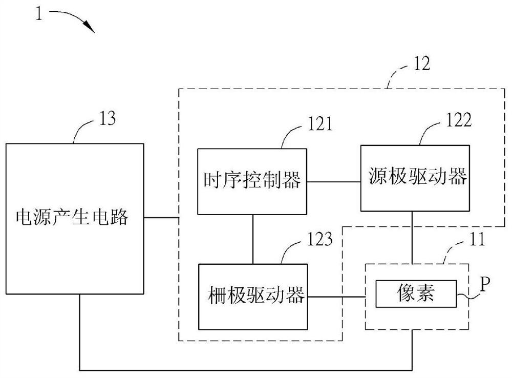
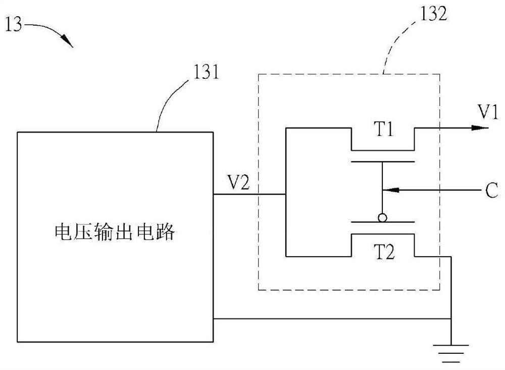
The application discloses a power generating circuit and a display device thereof. The power generation circuit outputs a first voltage and transmits it to a plurality of pixels of the display panel. The first voltage has a predetermined high voltage level. The power generation circuit includes a voltage output circuit and a voltage conversion circuit. The voltage output circuit outputs a second voltage , the voltage conversion circuit is electrically connected to the voltage output circuit, and outputs the first voltage according to the second voltage and a control signal; wherein, within one period of the first voltage, the control signal increases the first voltage output by the voltage conversion circuit to a predetermined high voltage level, and make the highest voltage level of the last falling edge of the first voltage less than the predetermined high voltage level. The application can effectively improve the capacitive coupling effect and make the display effect more excellent.

Description

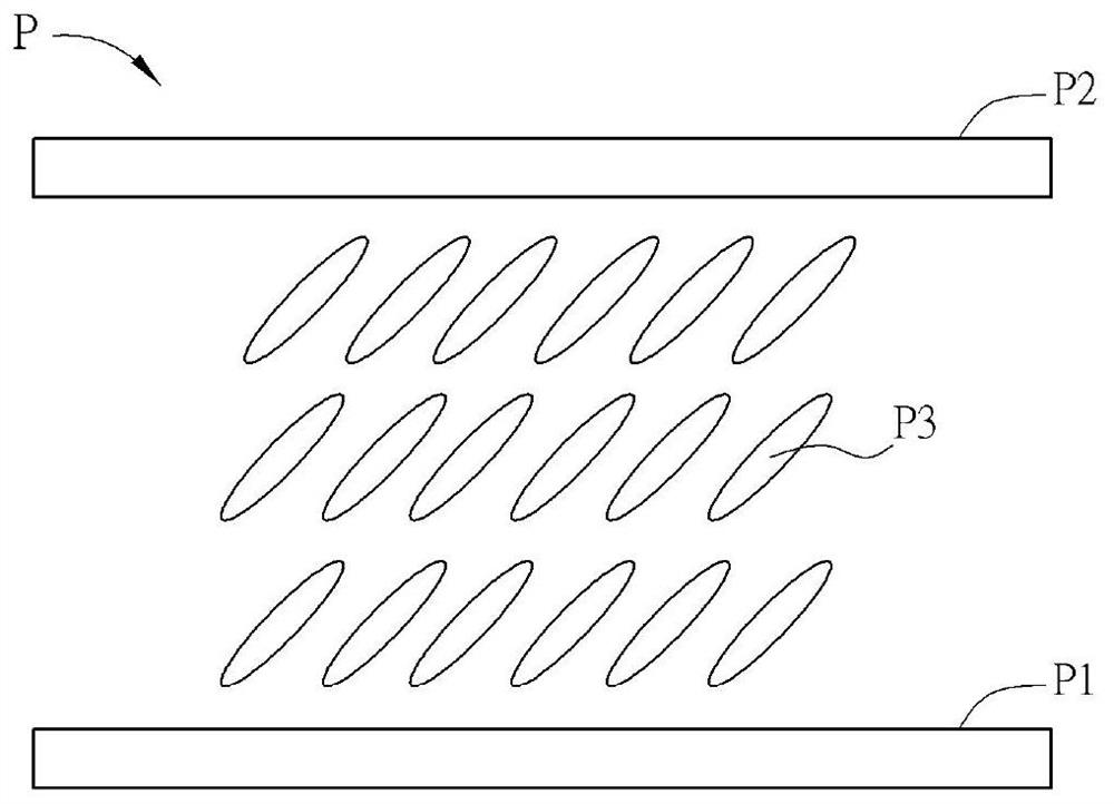
technical field [0001] The present application relates to a power generating circuit, in particular to a power generating circuit and a display device thereof which can effectively improve the capacitive coupling effect. Background technique [0002] With the development of liquid crystal display technology, liquid crystal displays are gradually popularized. The liquid crystal display mainly uses the electric field to control the rotation of the liquid crystal molecules of the pixels, so that the light can pass through the liquid crystal molecules to display images. [0003] A thin film transistor (thin film transistor, TFT) is a key component for driving pixels in a liquid crystal display device. In the known technology, the electronic channel of the TFT is formed at the interface below the semiconductor layer, while the source / drain is at the upper interface of the semiconductor layer. Therefore, the electronic channel of the TFT must pass through the semiconductor layer ...

Claims


Application Information

Patent Timeline
Patent Type & Authority Patents(China)
IPC IPC(8): G09G3/36H02M3/158
CPCG09G3/3648G09G3/3696H02M3/158
Inventor 李汶欣叶利丹
Owner HKC CORP LTD
Learn More