Liquid crystal display

a liquid crystal display and display screen technology, applied in the field of liquid crystal display, can solve the problems of display quality deterioration, display quality deterioration, interference fringes (or beat noise) on the display screen, etc., to reduce the variation of the voltage of |vsvcom|, prevent interference fringes on the display, and reduce the effect of switching nois

Inactive Publication Date: 2008-04-22
MITSUBISHI ELECTRIC CORP
View PDF7 Cites 2 Cited by
  • Summary
  • Abstract
  • Description
  • Claims
  • Application Information

AI Technical Summary

Benefits of technology

[0019]According to the present invention, phases of the switching frequency of the voltage supplied from the DC / DC converter and the control signal supplied from the timing control circuit are synchronized, thereby reducing variation of the voltage of |VS−VCOM| for each gate line, that is, switching noise effectively and preventing interference fringes on the display so that high-quality display is obtained.
[0020]Moreover, the oscillation frequency of the inverter for supplying voltage to the lamp and the dimmer signal are in phase with the control signal, thereby enables to reduce the frequency interference to prevent the interference fringes, therefore, high quality image can be displayed.
[0021]By carrying out phase matching of all signals in LCD such as control signal, switching frequency of the DC / DC converter, further, oscillation frequency and dimmer signal of inverter, it becomes possible to reduce the noise caused by variation in voltage applied to the display to prevent the interference fringe on the display, so that high-quality image can be obtained.

Problems solved by technology

That is, even if the same signal line voltage VS is applied, a voltage |VS−VCOM| applied to liquid crystal substances varies with each gate line, results in an interference fringes (or beat noise) on the display screen.
Therefore, since the value of |VS−VCOM|=V are not steady in each gate line, there appears interference fringes (or beat noise) on the display so that the display quality is deteriorated.
In addition, a dimmer signal of the inverter shall not synchronized with a signal line voltage VS and a switching frequency of the DC / DC converter so that the display quality is deteriorated.

Method used


Image

  • Liquid crystal display
  • Liquid crystal display
  • Liquid crystal display

Examples


embodiment 1

[0029]The present embodiment is characterized in that the switching operation of the DC / DC converter is synchronized with the control signal output from the timing control circuit.

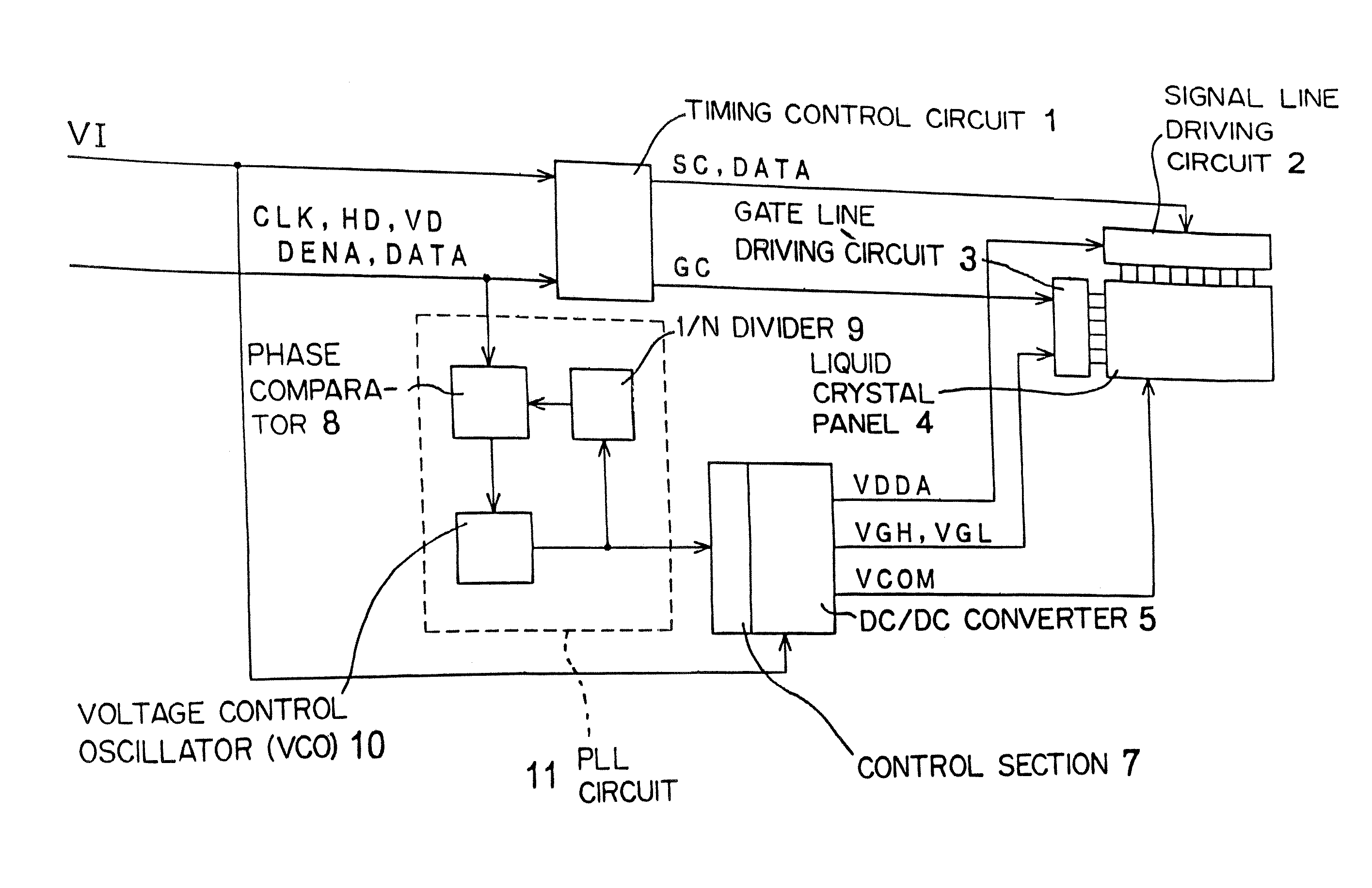
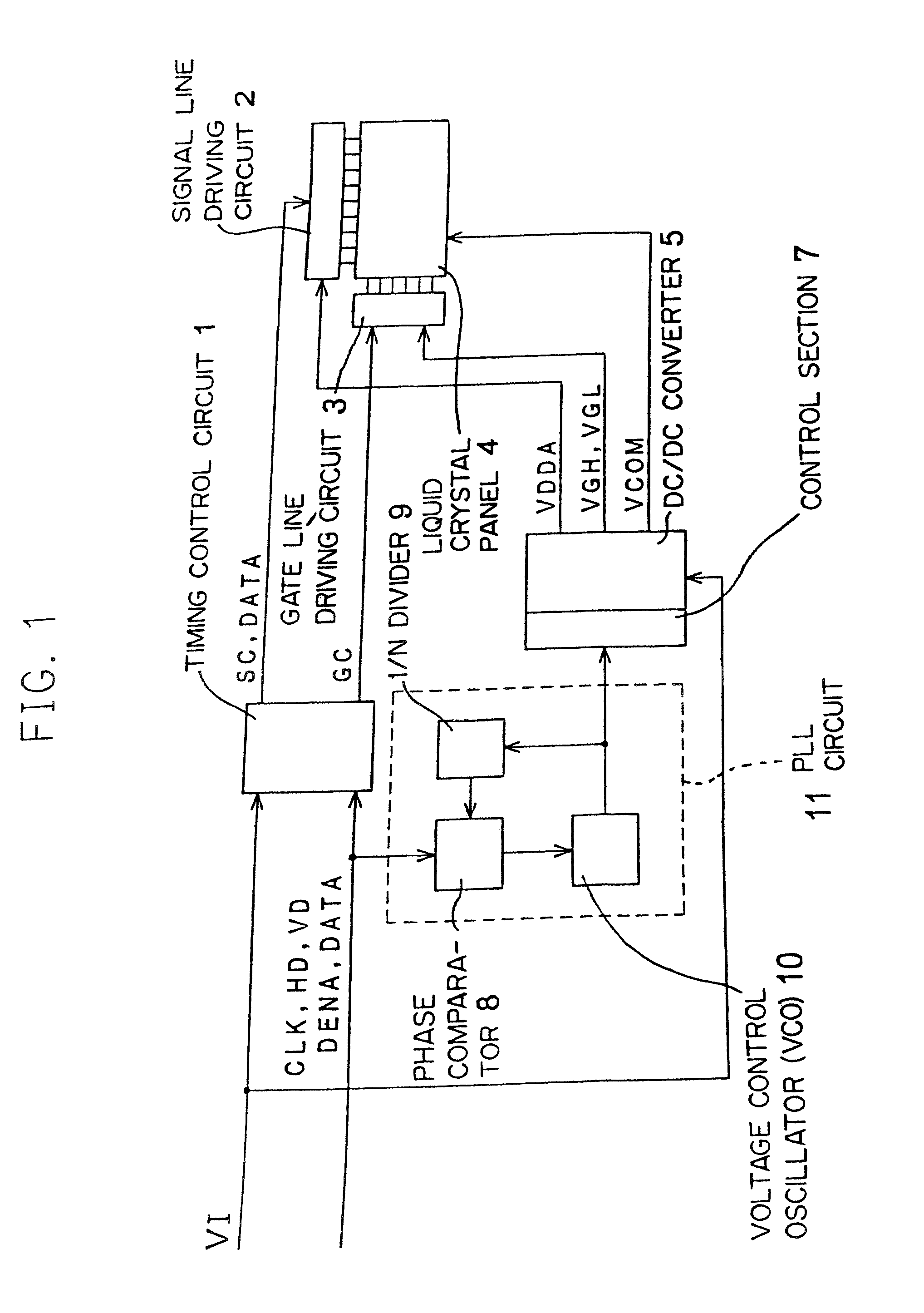
[0030]The method how the switching operation of the DC / DC converter is synchronized with the control signal output from the timing control circuit is explained with reference to FIG. 1.

[0031]FIG. 1 shows a block diagram of a LCD according to the present embodiment. A clock signal CLK, a horizontal synchronous signal HD, a vertical synchronous signal VD, a data enabling signal DENA for specifying display period, a data signal DATA and the like are input into a timing control circuit 1. These signals are previously synchronized with each other. In the timing control circuit 1, control signal SC for a signal line driving circuit 2 and control signal GC for a gate line driving circuit 3 are generated and are input into each drive circuit.

[0032]Moreover, a voltage VI is externally supplied to the timing control...

embodiment 2

[0039]An example where a backlight and an inverter which supplies voltage to a lamp of the backlight are provided is shown in the present embodiment.

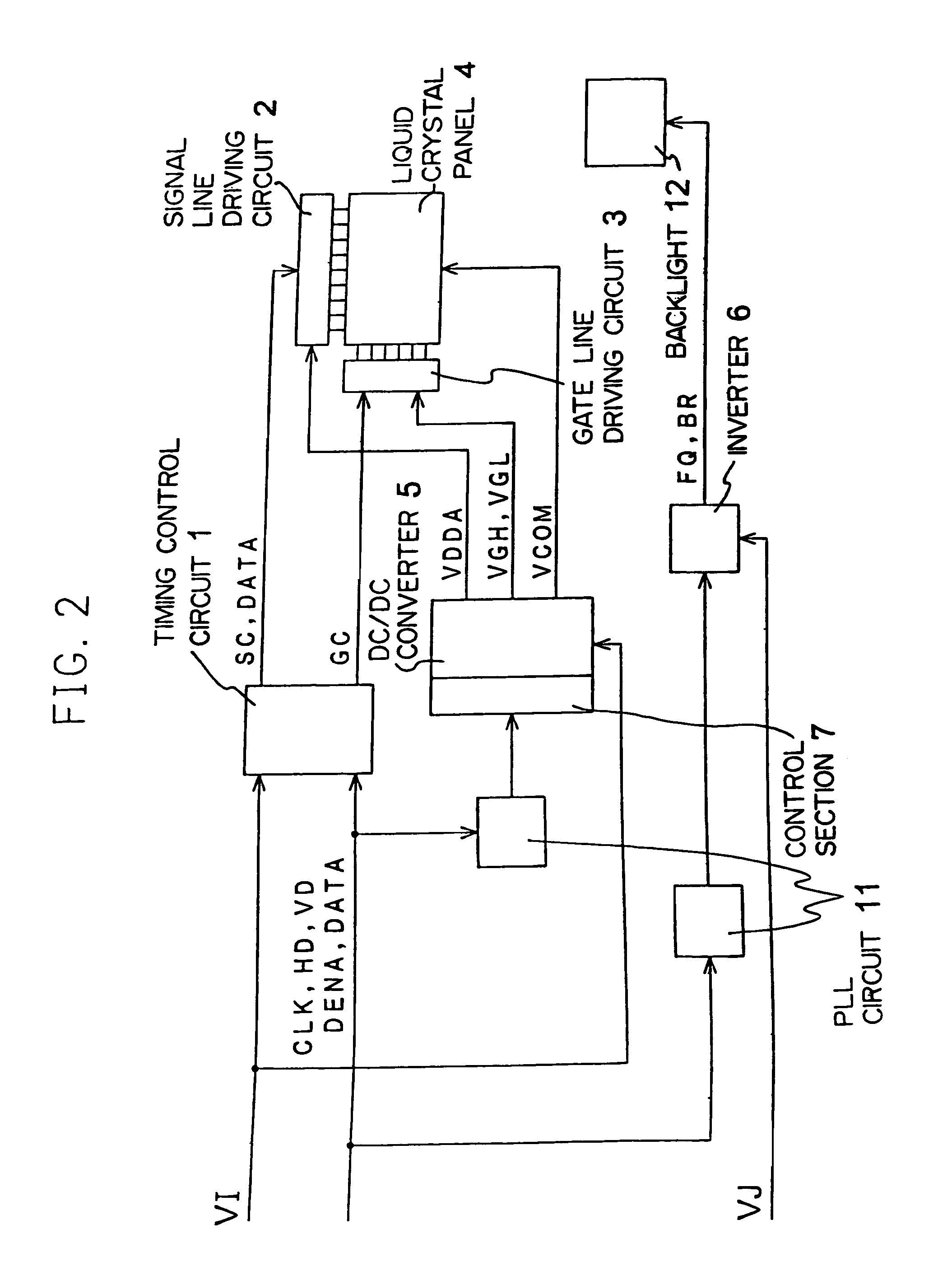
[0040]FIG. 2 shows the block diagram of LCD of the present embodiment. As described in Embodiment 1, either of the input signals input into timing control circuit 1 is also input into the PLL circuit 11 and by controlling the DC / DC converter S with the output signal from the PLL circuit 11, the switching frequency of the DC / DC converter 5 is in phase with the phase of control signal SC and GC.

[0041]Furthermore, either of the input signals is input into another PLL circuit 11 and the inverter 6 is oscillated and outputs voltage for backlight according to the output signal from this PLL circuit 11. By doing this, the oscillating frequency of the inverter 6 can be synchronized with the control signal SC and GC.

[0042]By phase-matching the oscillating frequency of the inverter 6 and the control signal, the voltage of |VS−VCOM| becomes consta...


PUM

PropertyMeasurementUnit
voltagesaaaaaaaaaa
voltageaaaaaaaaaa
switching frequencyaaaaaaaaaa

Abstract

A liquid crystal display according to the present invention can prevent interference fringe on a display panel due to a switching noise of a DC / DC converter, therefore a high-quality image can be displayed. Either of input signals for a timing control circuit is also supplied to a PLL circuit and the DC / DC converter is controlled by an output signal of the PLL circuit, thereby enables to synchronize a switching frequency of the DC / DC converter and control signal.

Description

CROSS-REFERENCE TO RELATED APPLICATIONS[0001]This is a divisional application of U.S. application Ser. No. 09 / 972,938, filed Oct. 10, 2001, now U.S. Pat. No. 6,822,633, and is based upon and claims the benefit of priority from prior Japanese Patent Application No. 2000-327208, filed on Oct. 26, 2000, the entire contents of which are incorporated herein by reference.BACKGROUND OF THE INVENTION[0002]The present invention relates to a liquid crystal display (hereinafter “LCD”), especially to a driving circuit of LCD and an inverter for supplying voltage to a backlight of LCD.[0003]A display panel of a LCD consists of a lot of pixels arranged into a form of matrix, that is, rows and columns. Each pixel in the display panel includes a switching element, such as a thin film transistor (hereinafter “TFT”), connected to respective gate line and signal line. In addition, a pixel electrode is connected to the TFT. When a TFT is turned ON by an electric signal on the respective gate line, a vo...

Claims


Application Information

Patent Timeline
Patent Type & Authority Patents(United States)
IPC IPC(8): G09G3/36G09G5/00G02F1/1335G02F1/133G02F1/13357G09G3/20G09G3/34H04N5/66
CPCG09G3/3406G09G3/3696G09G3/3648G09G2320/02G09G2320/064G09G2330/02G09G2330/06
Inventor TAKAOKA, HIRONORIOURA, HISAHARUSHIBATA, SUSUMUIKEMOTO, TETSUYA
Owner MITSUBISHI ELECTRIC CORP
Why Eureka
Try Eureka