
Display device and method for driving the same

Inactive Publication Date: 2016-02-11
TCL CHINA STAR OPTOELECTRONICS TECH CO LTD
View PDF3 Cites 1 Cited by
  • Summary
  • Abstract
  • Description
  • Claims
  • Application Information

AI Technical Summary

Benefits of technology

The present patent allows for the electrical connection of pixel electrodes in a display process. This is achieved by enabling an additional scan line in advance, which neutralizes the voltages on two pixel electrodes with opposite polarities. Afterward, data signals are input to the pixel electrodes through data lines, and the voltages on them are charged from zero to predetermined grayscales. This reduces voltage variation and improves charging speed, meeting the requirements for high refresh rate and resolution.

Problems solved by technology

On the other hand, due to existence of impurity molecules in liquid crystal molecules, the liquid crystal molecules are easily subject to polarization if driven under a DC voltage for a long time, thus affecting the display effects thereof.
The voltage of pixel electrode varies rather greatly, and therefore requires a rather long charging time.
That is, only a low charging speed can be obtained.
However, existing liquid crystal displays are of low charging speed, especially in the case of the dot reversion drive mode, where the requirements of high refresh rate and resolution can hardly be satisfied.

Method used


Image

  • Display device and method for driving the same
  • Display device and method for driving the same
  • Display device and method for driving the same

Examples


embodiment 1

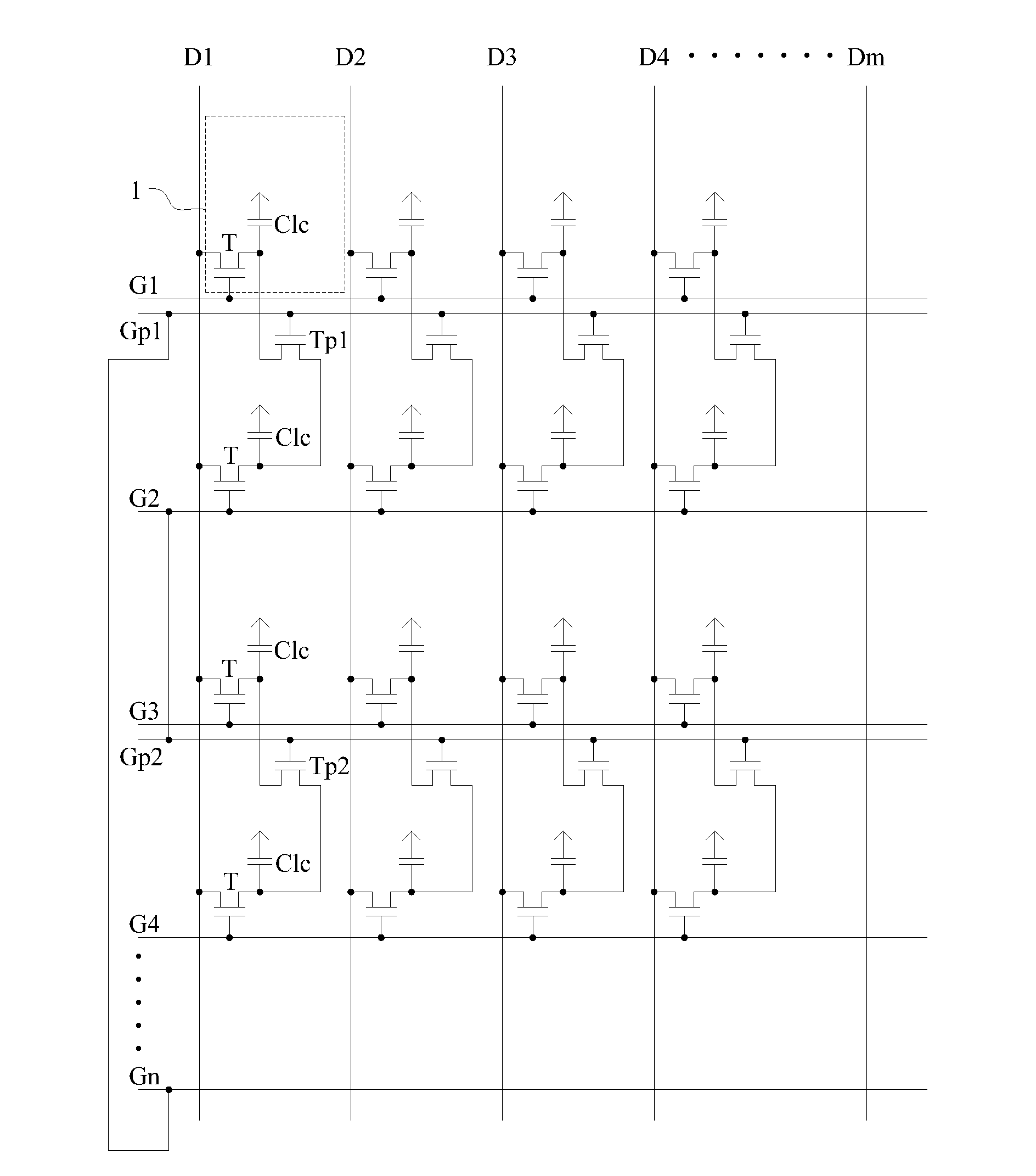
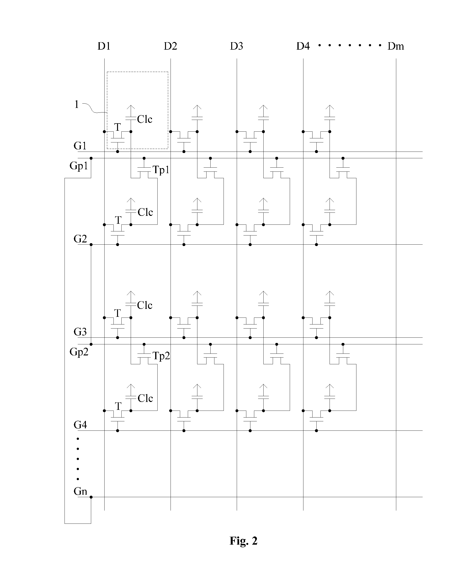
[0034]As indicated in FIG. 2, this embodiment of the present disclosure provides a display device, which can be a liquid crystal display television, a liquid crystal display, a mobile phone, a tablet personal computer, etc. The display device comprises n scan lines and m data lines that are staggered with each other horizontally and vertically, and n×m sub-pixel units 1 defined by the scan lines and data lines. The sub-pixel units each comprise a thin film transistor (TFT) and a pixel electrode, wherein the thin film transistor T has its gate connected to a respective scan line, its source connected to a respective data line, and its drain connected to the pixel electrode. When the scan line is enabled, the data signal on the respective data line can be input into the pixel electrode via the thin film transistor T, and a liquid crystal capacitor C1c is formed between the pixel electrode and the common electrode.

[0035]The display device further comprises an additional scan line and a...

embodiment 2

[0049]As indicated in FIG. 3, this embodiment of the present disclosure provides a display device, comprising n scan lines and m data lines that are staggered with each other horizontally and vertically, and n×m sub-pixel units 1 defined by the scan lines and data lines. The sub-pixel units each comprise a thin film transistor (TFT) and a pixel electrode, wherein the thin film transistor T has its gate connected to a respective scan line, its source connected to a respective data line, and its drain connected to the pixel electrode. When the scan line is enabled, the data signal on the respective data line can be input into the pixel electrode via the thin film transistor T, and a liquid crystal capacitor C1c is formed between the pixel electrode and the common electrode.

[0050]The display device further comprises an additional scan line and an additional TFT, wherein the additional TFT has its gate connected to the additional scan line, its source connected to the pixel electrode of...


PUM


Abstract

The present disclosure discloses a display device and a method for driving the same, which belongs to the field of display technology and therefore solves the technical problem of low charging speed of a liquid crystal display in the prior art.The display device comprises a plurality of scan lines and data lines that are staggered with each other vertically and horizontally, a plurality of sub-pixel units defined by the scan lines and data lines, an additional scan line, and an additional TFT, wherein the additional TFT has its gate connected to the additional scan line, its source connected to the pixel electrode of a first sub-pixel unit, and its drain connected to the pixel electrode of a second sub-pixel unit, and wherein the polarities of voltages on the pixel electrodes of the first sub-pixel unit and the second sub-pixel unit are opposite to each other.

Description

[0001]The present application claims benefit of Chinese patent application CN 201410253886.0, entitled “Display device and method for driving the same” and filed on Jun. 9, 2014, the entirety of which is incorporated herein by reference.FIELD OF THE INVENTION[0002]The present disclosure relates to the field of display technology, in particular to a display device and a method for driving the same.BACKGROUND OF THE INVENTION[0003]As the display technology develops, liquid crystal displays have become the most commonly used display device.[0004]In the display process of a liquid crystal display, the scan lines (gate lines) each are successively enabled. During a period when one scan line is enabled (during one scan cycle), the data lines each input data signals to the pixel electrodes located in this line of sub-pixel units, i.e., to charge the liquid crystal capacitors located in this line of sub-pixel units.[0005]On the other hand, due to existence of impurity molecules in liquid cr...

Claims


Application Information

Patent Timeline
IPC IPC(8): G09G3/36
CPCG09G3/3677G09G2300/0426G09G2310/0278G09G3/3614G09G3/3659G09G2300/0814G02F1/13624
Inventor XU, XIANGYANG
Owner TCL CHINA STAR OPTOELECTRONICS TECH CO LTD
Learn More