Damping of LC ringing in IC (integrated circuit) power distribution systems

a technology of integrated circuits and power distribution systems, applied in pulse manipulation, pulse techniques, instruments, etc., can solve problems such as degrading the reliability of on-chip circuits, sudden changes in power demand, and functional design failures, and achieve the effect of dampening the voltage variation

Inactive Publication Date: 2005-11-08
INT BUSINESS MASCH CORP
View PDF8 Cites 2 Cited by
  • Summary
  • Abstract
  • Description
  • Claims
  • Application Information

AI Technical Summary

Benefits of technology

[0006]The present invention provides a structure, comprising (a) an IC power distribution circuit; (b) a resistor electrically connected in series with the circuit; (c) an electrical switch electrically connected in parallel with the resistor; and (d) a controller, electrically connected to the electrical switch, wherein the controller is configured to open the electrical switch to reduce the transient voltage variation across the circuit.
[0007]The present invention provides a method, comprising the steps of (a) providing an IC power distribution circuit, a resistor electrically connected in series with the circuit, an electrical switch electrically connected in parallel with the resistor, and a controller electrically connected to the electrical switch; and (b) causing the controller to open the electrical switch to reduce the transient voltage variation across the circuit.
[0010]The present invention also provides methods for operating such structures to dampen the variation of voltage across an IC power distribution system.

Problems solved by technology

In typical IC implementations, circuit activity may be characterized by sudden changes in power demand.
However, any subsequent and significant changes in chip power demand will re-introduce the LC ringing and the corresponding modulation of the power supply voltage.
This transient “power noise” can induce functional design failures, or even degrade the reliability of the on-chip circuits.
Both outcomes are undesirable.

Method used


Image

  • Damping of LC ringing in IC (integrated circuit) power distribution systems
  • Damping of LC ringing in IC (integrated circuit) power distribution systems
  • Damping of LC ringing in IC (integrated circuit) power distribution systems

Examples


Embodiment Construction

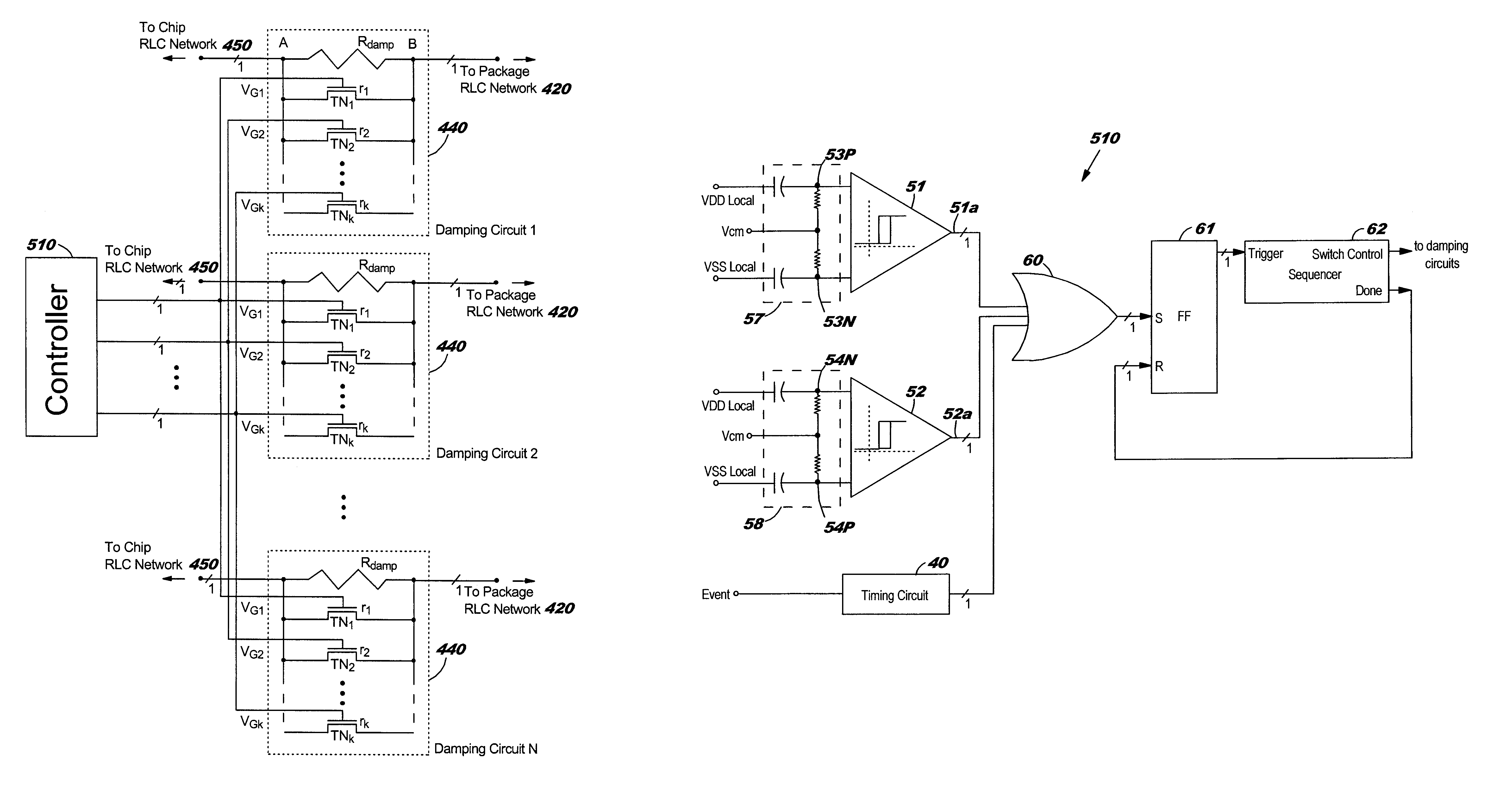
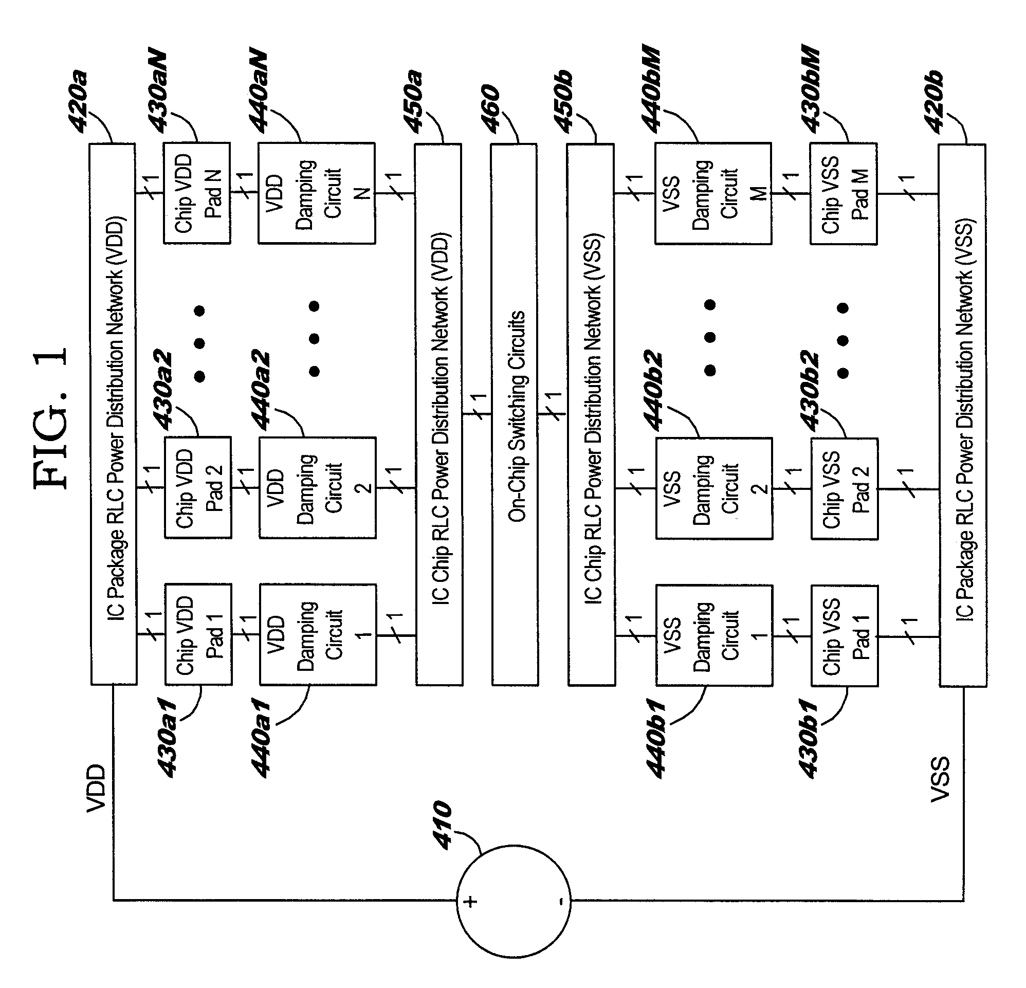
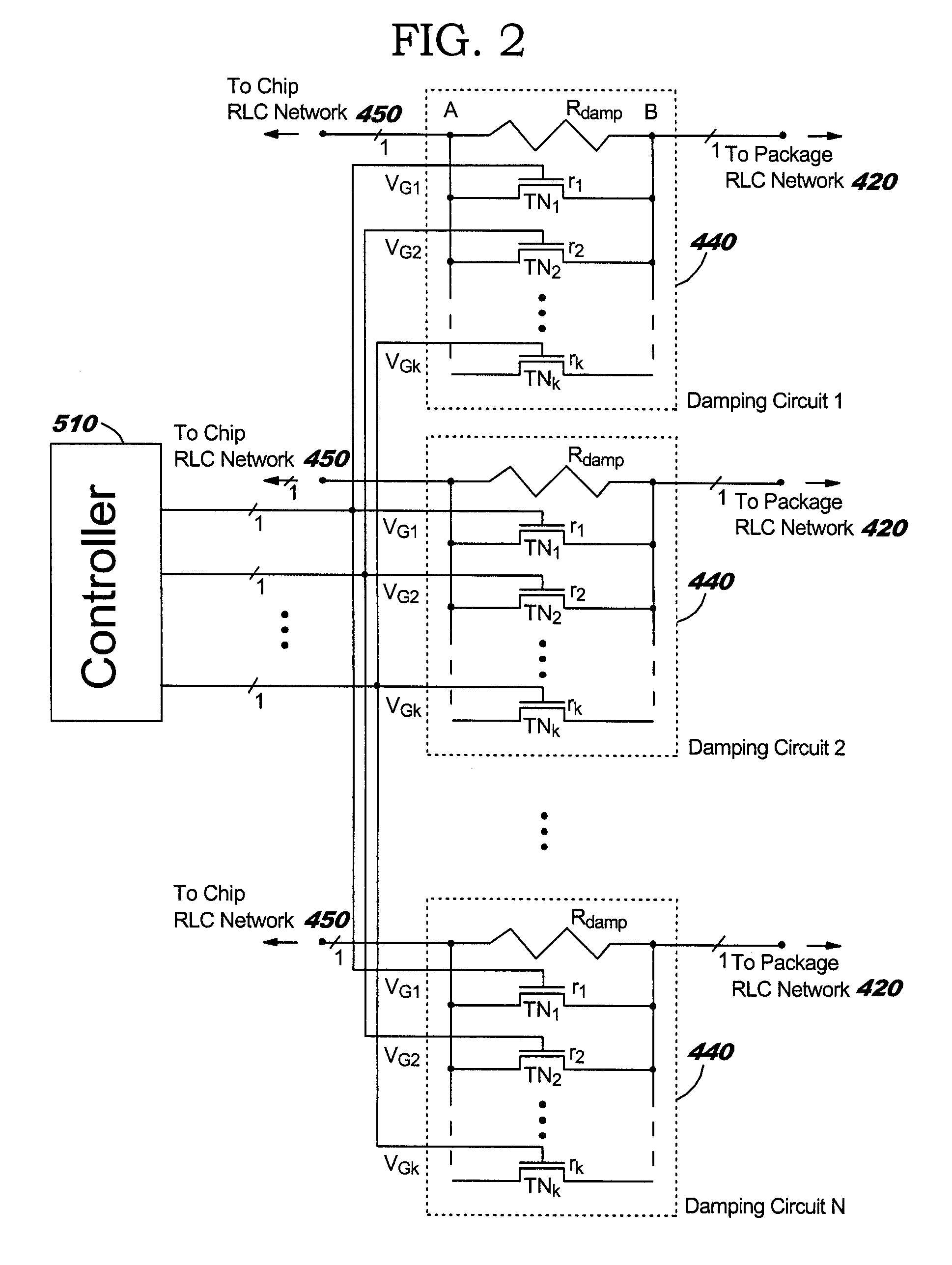
[0014]FIG. 1 illustrates an IC configuration comprising an ideal power supply 410, RLC circuits representing the (resistive, inductive, and capacitive) parasitics of the package 420, and chip VDD and VSS power distribution networks, on-chip switching circuits 460, and a plurality of damping circuits 440 inserted between the package 420 and chip RLC power structures 450, in accordance with embodiments of the present invention.

[0015]One or a plurality of damping circuit(s) 440a and the package “VDD” RLC circuit 420a are electrically connected to one, a subset, or all of the chip VDD pads 430a. The damping circuit(s) 440a connected to the package “VDD” RLC circuit 420a are also connected to the chip “VDD” RLC circuit 450a. One or a plurality of damping circuit(s) 440b and the package “VSS” RLC circuit 420b are electrically connected to one, a subset, or all of the chip VSS pads 430b. The damping circuit(s) 440b connected to the package “VSS” RLC circuit 420b are also connected to the c...


PUM


Abstract

A structure and method for damping LC (inductance-capacitance) ringing in integrated circuit (IC) power distribution systems. The structure comprises a resistance electrically connected in parallel with a plurality of electrical switches. The resistance and electrical switches are electrically connected in series with the package and on-chip power distribution circuit. When on-chip switching activity creates a sudden and appreciable change in IC power demand the electrical switches are opened to temporarily increase the resistance in series with the power supply. This serves to dampen the power-distribution LC ringing. Later, the electrical switches are closed to shunt the series resistance and reduce the level of steady-state voltage drop in the power structure.

Description

BACKGROUND OF INVENTION[0001]1. Technical Field[0002]The present invention relates to damping of LC (inductance-capacitance) ringing effects, and more specifically, to damping of LC ringing effects in IC (Integrated Circuit) power distribution systems.[0003]2. Related Art[0004]In typical IC implementations, circuit activity may be characterized by sudden changes in power demand. For example, the use of clock gating in sequential circuits can suddenly induce or eliminate logic-signal switching in large circuit blocks, by activating or suppressing the application of clock signals to every flip-flop in a clock domain. Whenever the domains are turned on and off, the corresponding and abrupt change in power demand generates a system step response, characterized by an oscillating transient voltage variation across the chip power distribution system (board, package, and on-chip power grid). The response period is a strong function of the power system's inductance and capacitance, and the r...

Claims


Application Information

Patent Timeline
Patent Type & Authority Patents(United States)
IPC IPC(8): G05F3/02G05F1/10H03L5/00H03K17/16
CPCG11C5/14H01L23/50H03K17/164H01L2924/0002H01L2924/00
Inventor BONACCIO, ANTHONY R.HAAR, ALLEN P.SORNA, MICHAEL A.WEMPLE, IVAN L.WYATT, STEPHEN D.
Owner INT BUSINESS MASCH CORP
Why Eureka
Try Eureka