User-side distributed energy storage device

A distributed energy storage, user-side technology, applied to circuit devices, electrochemical generators, sustainable buildings, etc. Improve the power consumption experience, improve the service life, and the effect of simple installation

Active Publication Date: 2020-11-13
STATE GRID ZHEJIANG ELECTRIC POWER CO LTD JIAXING POWER SUPPLY CO
View PDF6 Cites 2 Cited by
  • Summary
  • Abstract
  • Description
  • Claims
  • Application Information

AI Technical Summary

Problems solved by technology

[0005] The present invention mainly solves the problem that the distributed energy storage device in the existing technology cannot find faults in time and cannot handle the faults in time; it provides a user-side distributed energy storage device to realize the storage of excessive power and insufficient power in the power grid Timely supplement, comprehensive monitoring of distributed energy storage devices, effective detection and timely resolution of faults, reducing grid equipment costs

Method used


Image

  • User-side distributed energy storage device
  • User-side distributed energy storage device
  • User-side distributed energy storage device

Examples


Embodiment 1

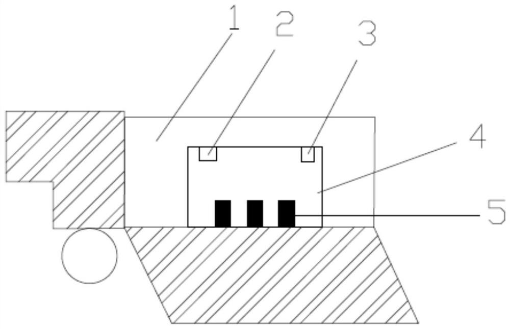
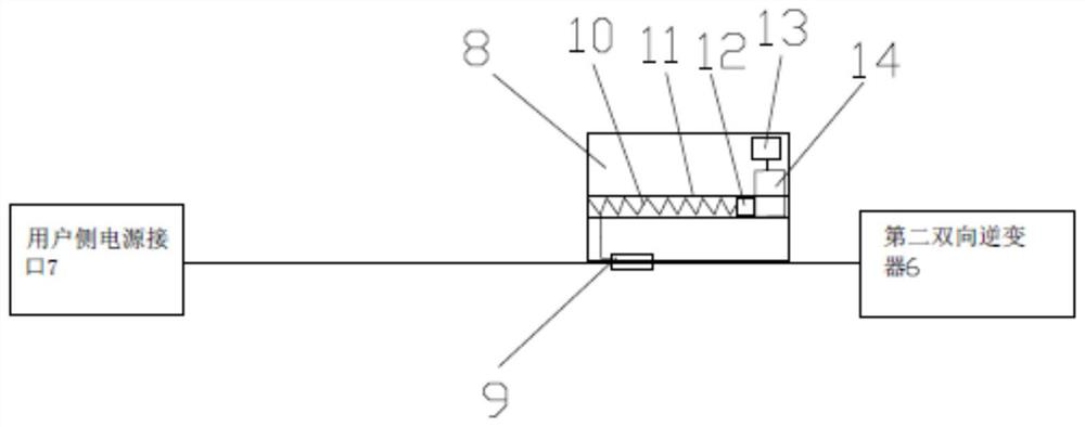
[0020] Embodiment 1: A user-side distributed energy storage device, such as figure 1 As shown, it includes a mobile device 1, an energy storage box, a fire protection system, an information sending module 21, a heating device and a heat dissipation device. The energy storage box is installed on the mobile device 1, and the fire protection system is installed on the energy storage box; the energy storage box includes a box Body 4, several battery modules, several battery holders 5, battery management system 2, first bidirectional inverter, second bidirectional inverter 6 and monitoring system 3; several battery holders 5 are distributed and installed in the box body 4 The battery module is installed on the battery bracket 5, and several battery modules are connected to the battery management system 2; the grid-side power interface and the user-side power interface 7 are installed on the box body 4, and the input terminal of the first bidirectional inverter is connected to the gr...

Embodiment 2

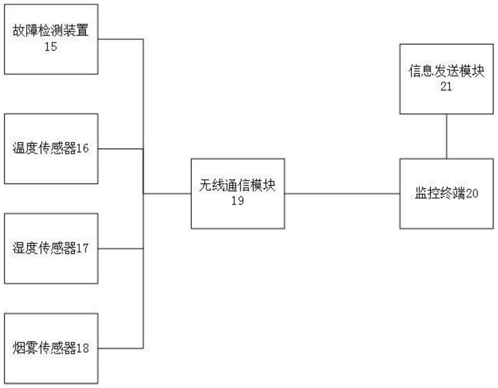
[0026] Embodiment 2, a user-side distributed energy storage device. Compared with Embodiment 1, this embodiment differs in that the monitoring system 3 also includes a lighting device and a camera, and both the camera and the lighting device communicate with the monitoring terminal through a wireless communication module 19. 20 connections, the lighting device includes a track, a motor, a pulley, a pole, a power supply device and an LED lamp, the track is installed on the inner wall of the box body 4, the motor is installed on one side of the track, and the control end of the motor communicates with the monitoring terminal via the wireless communication module 19 20 connections, the output end of the motor is connected to the pulley, the pulley matches the track, the pole is installed on the pulley, the power supply device is installed on one side of the pole, the LED light is installed on the pole, and the LED light is connected to the power supply device.

[0027] In a specif...


PUM


Abstract

The invention discloses a user-side distributed energy storage device, which comprises a mobile device, an energy storage box and a fire extinguishing system, and is characterized in that the energy storage box is mounted on the mobile device, and the fire extinguishing system is mounted on the energy storage box; the energy storage box comprises a box body, a plurality of battery modules, a plurality of battery supports, a battery management system, a first bidirectional inverter, a second bidirectional inverter and a monitoring system. The plurality of battery supports are distributed and mounted in the box body; the battery modules are mounted on the battery supports, and the plurality of battery modules are connected with the battery management system; and the box body is provided witha power grid side power interface and a user side power interface. Through the energy storage box, timely regulation and control of power grid power utilization are realized, and the power utilization experience of a user is improved; by arranging a heating device and a heat dissipation device, the environment in the energy storage box is kept in a constant-temperature state, and the service lifeof the battery module is prolonged; and through the fault detection device, the fault type is detected more accurately, the device is simple, and the detection range is wide.

Description

technical field [0001] The invention relates to the technical field of battery energy storage, in particular to a user-side distributed energy storage device. Background technique [0002] Distributed energy storage is a kind of energy storage that is mainly installed on the user side or the distributed generation side. It is mainly used to store excess distributed power generation energy and stabilize the fluctuation of distributed power generation output to reduce the impact on the distribution network. [0003] At present, the power grid is gradually using wind power and solar power for power generation. At certain moments, the generated power is too much, and the power stored in the energy storage station cannot be stored after reaching the upper limit, resulting in the loss of part of the energy. , there are some special time periods, users are in peak power consumption, and power consumption increases sharply, resulting in the risk of insufficient power supply. At the ...

Claims


Application Information

Patent Timeline
Patent Type & Authority Applications(China)
IPC IPC(8): H02J3/32H02J3/38H02J13/00H01M10/48H01M10/615H01M10/613A62C3/16
CPCH02J3/32H02J3/381H02J13/00002H02J13/00022H02J13/00026H01M10/48H01M10/615H01M10/613A62C3/16H02J2300/24H02J2300/28Y02B90/20Y04S20/12Y02E10/56Y02E60/10
Inventor 段军尹积军钱伟杰孙可陈鼎郁家麟斯建东沈曙明王培林王文华黄颖殷伟斌冯悦鸣吕勤张盛冯晓科徐冬生沈金青王磊陈理林春红丁一岷陈肖烈方唯张志芳曾建梁胡舟严耀良韩中杰车江嵘张勇莫加杰江锡忠沈超仲立军方景辉屠晓栋董刚孙献春唐锦江李春施海峰朱新郑朝明
Owner STATE GRID ZHEJIANG ELECTRIC POWER CO LTD JIAXING POWER SUPPLY CO
Why Eureka
Try Eureka