A combined straw collector

A collection machine and combined technology, applied in loaders, agricultural machinery and tools, agriculture, etc., can solve the problems of low operation efficiency, low throwing height, high operation efficiency, etc., and achieve high operation efficiency, large operation width, The effect of reducing energy consumption

Active Publication Date: 2022-04-29
陈孝中
View PDF13 Cites 0 Cited by
  • Summary
  • Abstract
  • Description
  • Claims
  • Application Information

AI Technical Summary

Problems solved by technology

[0003] The invention overcomes the shortcomings of the straw collecting machine, such as low height, short distance and low operation efficiency, and provides a combined straw collector, which collects straw and throws high height, long distance and high operation efficiency.

Method used


Image

  • A combined straw collector
  • A combined straw collector
  • A combined straw collector

Examples


Embodiment 1

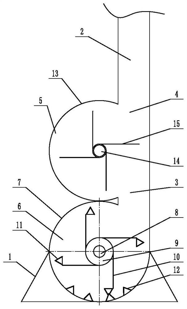
[0044] Embodiment 1: A kind of combined straw collector (see attached figure 1 ), including the feed cover 1, the throwing pipe 2, the fan combination unit installed between the feed cover and the throwing pipe, the fan combination unit includes two collection fans arranged up and down, and the collection fan is provided with a grass inlet 3 And the grass outlet 4, at least one collecting fan grass inlet is connected with the feeding hood, at least one collecting fan’s grass outlet is connected with the throwing pipe, the opening of the feeding hood is set downwards, and the collecting fan is arranged on the straw in the feeding hood. Collect and throw the straw to the throwing pipe, so that the straw is thrown outward from the throwing pipe.

[0045] The collecting fan above is the throwing fan 5, and the collecting fan below is the chopping fan 6. The grass inlet of the chopping fan is connected with the feed cover, and the grass outlet of the chopping fan is connected with ...

Embodiment 2

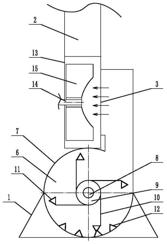
[0050] Embodiment 2: A kind of combined straw collector (see attached figure 2 ), its structure is similar to that of Embodiment 1, the main difference is that in this embodiment, the upper collection fan end face is provided with an axial feeding grass inlet, that is to say, the throwing blower adopts the axial feeding method, and the throwing blower in the throwing blower The throwing blade has a concave arc structure towards the edge of the grass inlet. Other structures are the same as in Embodiment 1.

Embodiment 3

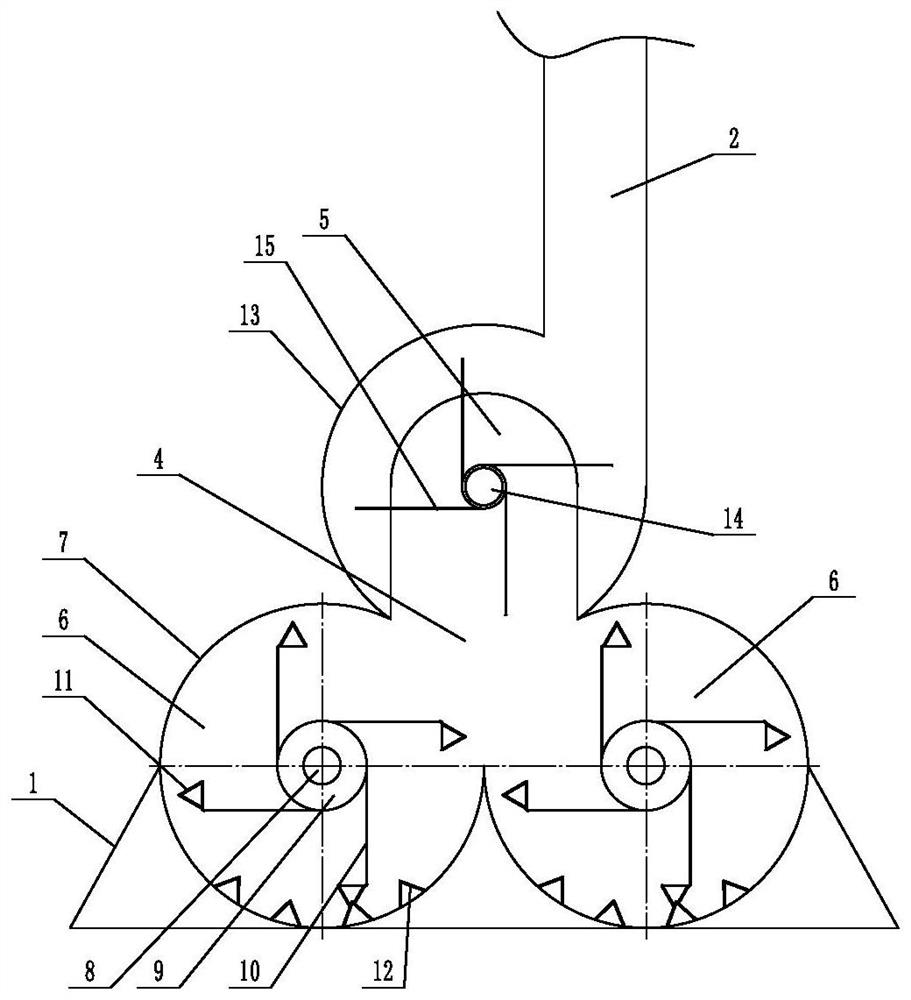
[0051] Embodiment 3: A kind of combined straw collecting machine (see attached image 3 ), including the feeding cover 1, the throwing pipe 2, the fan combination unit installed between the feeding cover and the throwing pipe, the fan combination unit includes three collecting fans, and the collecting fan is provided with a grass inlet 3 and a grass outlet Port 4, at least one collecting fan grass inlet is connected with the feeding hood, at least one collecting fan grass outlet is connected with the throwing pipe, the opening of the feeding hood is set downward, and the collecting fan collects the straw in the feeding hood and Throw the straw to the throwing pipe, so that the straw is thrown out from the throwing pipe

[0052] Two collecting fans are arranged side by side in the lower part of the fan combination unit, and one collecting fan is arranged in the upper part. The two collecting fans in the unit are chopping fans.

[0053] The chopping fan includes a casing 7, a ...


PUM


Abstract

The invention discloses a combined straw collector, which aims to solve the shortcomings of the straw collector, such as low height, short distance and low operation efficiency. The invention comprises a feeding hood, a throwing pipe, a blower combination unit installed between the feeding hood and the throwing pipe, the blower combination unit includes at least two collecting fans, and the collecting blower is provided with a grass inlet and a grass outlet, at least The grass inlet of a collecting fan is connected with the feeding hood, and the grass outlet of at least one collecting fan is connected with the throwing pipe, and the opening of the feeding hood is set downwards. The throwing pipe enables the stalks to be thrown outwards from the throwing pipe. The combined straw collector collects the straw and throws it with high height, long distance and high working efficiency.

Description

technical field [0001] The present invention relates to a kind of straw collecting equipment, more specifically, it relates to a combined straw collecting machine. Background technique [0002] At present, most of the straw collection in the field is carried out by the straw collector. The traditional straw collector uses a swing knife to pick up and crush the straw in the field, and then transports it to the blower fan for throwing by the auger. After the straw is crushed, it is conveyed by the auger. The conveying path is long and the conveying speed is slow. Contents of the invention [0003] The invention overcomes the shortcomings of the straw collecting machine, such as low collecting height, short distance and low working efficiency, and provides a combined straw collecting machine, which collects straw and throws high height, long distance and high working efficiency. [0004] In order to solve the above-mentioned technical problems, the present invention adopts t...

Claims


Application Information

Patent Timeline
Patent Type & Authority Patents(China)
IPC IPC(8): A01D87/00A01D87/10A01D89/00A01F29/01A01F29/02
CPCA01D87/0007A01D87/10A01F29/01A01F29/02A01D89/001
Inventor 陈孝中陈森森高翔陶雷陈黎卿
Owner 陈孝中
Why Eureka
Try Eureka