Automatic welding machine, welding tool and welding process

Inactive Publication Date: 2020-11-17
NANJING YUZHI INTELLIGENT TECH CO LTD
View PDF0 Cites 1 Cited by
  • Summary
  • Abstract
  • Description
  • Claims
  • Application Information

AI Technical Summary

Problems solved by technology

[0003] The purpose of the present invention is to solve the problem that the welding tool cannot lock the round pipe and the flange into a whole when welding between metals, so that when the round pipe rotates, there will be relative displacement between the flange and the round pipe The situation makes the welding effect poor and the welding is unqualified, and an automatic welding machine, welding tooling and welding process are proposed

Method used


Image

  • Automatic welding machine, welding tool and welding process
  • Automatic welding machine, welding tool and welding process
  • Automatic welding machine, welding tool and welding process

Examples


Embodiment 1

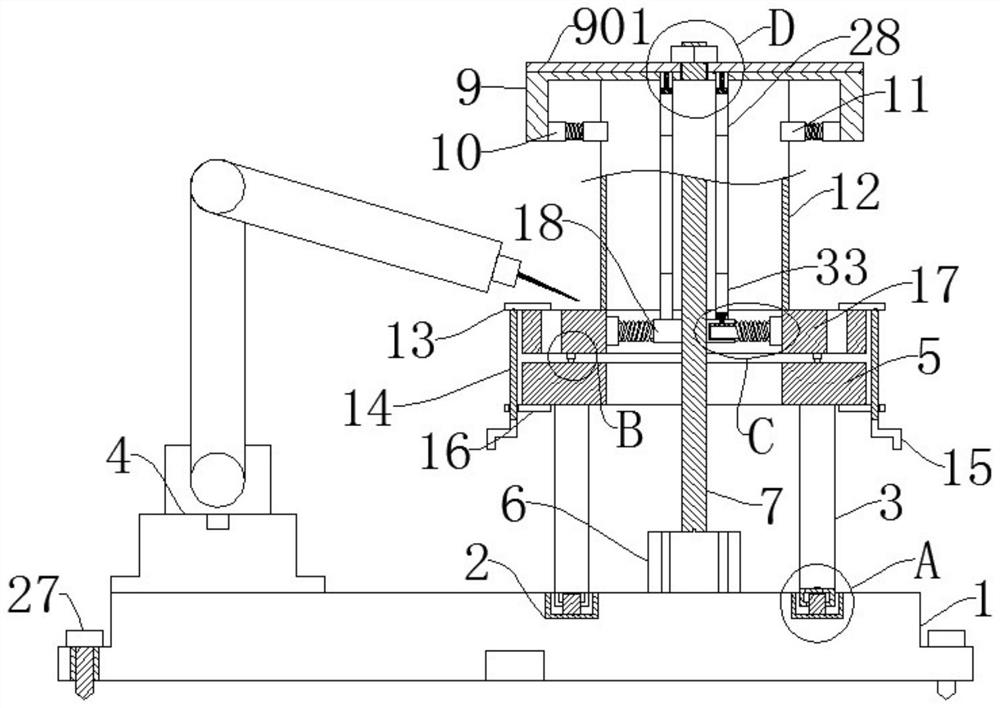
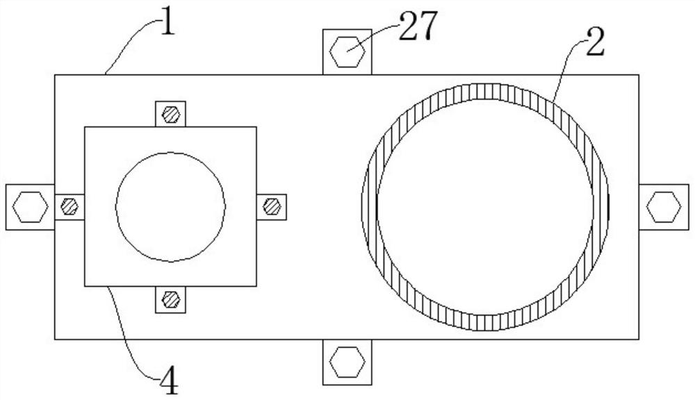
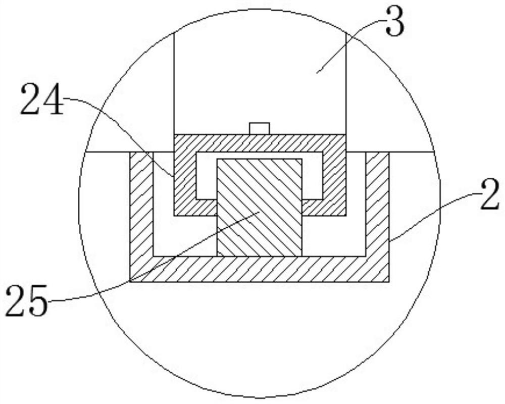
[0034] refer to Figure 1-9 , an automatic welding machine, a welding tool and a welding process, including a base 1, a circular track 2 is arranged on the base 1, a moving rod 3 is arranged on the circular track 2, and a supporting rod 24 is connected to the bottom of the moving rod 3 in rotation , the support rod 24 is rotatably connected with a roller 25, the moving rod 3 and the circular track 2 are slidably connected by the roller 25, the upper end of the moving rod 3 is fixedly connected with a circular disk 5, and the lower end of the circular disk 5 is fixedly connected with a second ring disk on both sides. A locking plate 16, a flange 17 is placed on the ring disc 5, a round pipe 12 is arranged on the upper end of the flange 17, a second locking plate 13 is connected to both sides of the upper end of the flange 17, and the first locking plate 16 passes through Threaded rotation is connected with threaded rod 14, and the upper end of threaded rod 14 is connected on th...

Embodiment 2

[0037] refer to Figure 1-9 , a kind of automatic welding machine, welding tooling and welding process, are basically the same as embodiment 1, further is: first sleeve 18 is fixedly connected with rotating rod 7 both sides, and first sleeve 18 is slidingly connected with first sleeve 18 The sliding rod 21, the end of the first sliding rod 21 away from the first sleeve 18 is fixedly connected with the limit block 23, the side of the limit block 23 far away from the first slide rod 21 is in close contact with the inner surface of the flange 17, the first slide The rod 21 is sleeved with a first spring 22, and the two ends of the first spring 22 are respectively fixedly connected with the first sleeve 18 and the stop block 23, and the first sleeve 18 is fixedly connected with a second hard tube 33, and the second The hard tube 33 is fixedly connected with a fixed block 29, the middle of the fixed block 29 is provided with an air inlet, the lower end of the fixed block 29 is prov...

Embodiment 3

[0040] refer to Figure 1-9 , a kind of automatic welding machine, welding tooling and welding process, are basically the same as embodiment 1, further is: the surface of semicircle arc plate 11, limit block 23 is all provided with rubber cushion, prevents semicircle arc plate 11 1. The limit block 23 scratches the contact surface with the round pipe 12 and the flange 17, improving the practicability of the welding tool.


PUM


Abstract

The invention discloses an automatic welding machine, a welding tool and a welding process, and belongs to the technical field of welding tools. The automatic welding machine comprises a base, whereina circular track is arranged on the base, a moving rod is arranged on the circular track, the moving rod is slidably connected to the circular track through rolling wheels, a circular ring disc is fixedly connected to the upper end of the moving rod, first locking plates are fixedly connected to the two sides of the lower end of the circular ring disc, a flange is placed on the circular ring disc, the upper end of the flange is provided with a circular pipe, and the two sides of the upper end of the flange are connected to second locking plates. According to the automatic welding machine, through arrangement of a nut and a first pressing plate, the circular pipe and the flange can be locked into a whole, and therefore when the circular pipe is rotated, the flange and the circular pipe canrotate at the same time, the situation that the flange and the circular pipe do not have relative displacement is avoided, and the welding quality is improved.

Description

technical field [0001] The invention relates to the technical field of welding equipment, in particular to an automatic welding machine, a welding equipment and a welding process. Background technique [0002] Nowadays, with the development of science and technology, there are many types of welding-related automatic machinery. The commonly used welding machines do not use the electrodes used in traditional welding, but use flux to weld the positions that need to be welded, and weld between the metals. When welding, the welding tool is indispensable, and the welding tool is a device used to fix the object to be welded. In the prior art, the welding machine is used for some special welding work such as the annular welding between the round pipe and the flange. Welding, the effect is not ideal, that is because the existing welding tool cannot lock the round pipe and the flange into a whole, so when the round pipe is rotated, the flange and the round pipe cannot be rotated at th...

Claims


Application Information

Patent Timeline
Patent Type & Authority Applications(China)
IPC IPC(8): B23K37/04
CPCB23K37/047
Inventor 李晓孙二南
Owner NANJING YUZHI INTELLIGENT TECH CO LTD
Why Eureka
Try Eureka