Automatic welding machine for micro-motor rotor

A fully automatic welding and micro-motor technology, applied in welding equipment, auxiliary devices, metal processing equipment, etc., can solve the problems of inability to fix, heavy workload of welding machine workers, inconvenient work, etc., to ensure product qualification rate, increase The practicability of the equipment and the effect of convenient processing and production

Inactive Publication Date: 2020-11-27
江苏银溢电机科技有限公司
View PDF7 Cites 0 Cited by
  • Summary
  • Abstract
  • Description
  • Claims
  • Application Information

AI Technical Summary

Problems solved by technology

[0002] With the development of society and economy, people's living standards are constantly improving, and science and technology are constantly developing and innovating. Various high-tech are constantly being applied to actual production and manufacturing. Welding machines use various fusible alloys to join For parts equipment, the melting point of solder is lower than that of the material to be welded, so that the parts will be welded through intermolecular contact on the surface without being melted. The invention of the welding machine has played an important role in the development of the industry. However, the functions of the welding devices on the market are often similar. When welding the motor rotor, the motor rotor to be welded cannot be fixed, which makes it very inconvenient and time-consuming to work, which makes the workload of the welder workers become very large. , very inefficient

Method used


Image

  • Automatic welding machine for micro-motor rotor
  • Automatic welding machine for micro-motor rotor
  • Automatic welding machine for micro-motor rotor

Examples


Embodiment Construction

[0018] In order to further explain the embodiments, the present invention is provided with drawings. These drawings are a part of the disclosure of the present invention. They are mainly used to illustrate the embodiments, and can cooperate with the relevant descriptions in the specification to explain the operating principles of the embodiments. Those of ordinary skill in the art should be able to understand other possible implementations and advantages of the present invention from these contents. The components in the figure are not drawn to scale, and similar component symbols are usually used to indicate similar components.

[0019] According to an embodiment of the present invention, a fully automatic welding machine for a rotor of a micro motor is provided.

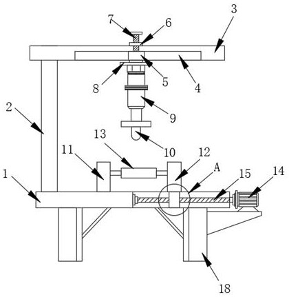
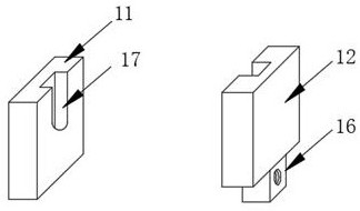
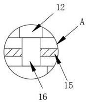
[0020] The present invention will now be further described with reference to the drawings and specific embodiments, such as Figure 1-3 As shown, an automatic welding machine for a micro-motor rotor according to an embo...


PUM


Abstract

The invention discloses an automatic welding machine for a micro-motor rotor. The machine comprises a base, a supporting column, a horizontal plate, a sliding groove and a sliding block, wherein the base is fixedly installed with supporting legs on both sides of the bottom end, the supporting column is installed on one side of the upper end of the base, the top of the supporting column is installed with a horizontal plate, the bottom surface of the horizontal plate is provided with the sliding groove, the sliding block is slidingly installed on the sliding groove, a bolt is installed on the top of the sliding block, a nut is installed on the bolt, and the bottom surface of the sliding block is fixedly installed with a mounting plate. The automatic welding machine realizes the left and right movement of a hydraulic cylinder through the coordinated use of the set sliding groove, sliding block, nut and bolt, thereby facilitating a welding head to be aligned with a welding wire groove of the rotor of the motor to be welded, and improving the accuracy of welding. When the sliding block needs to be moved, only the sliding block needs to be pushed to move in the sliding groove, and when the butt welding head is ready to be welded to the rotor, the worker manually turns the nut to make the nut lock and fix the sliding block, thereby preventing its movement from affecting the welding quality.

Description

Technical field [0001] The invention relates to a welding device, in particular to an automatic welding machine for a micro-motor rotor, and belongs to the technical field of motor rotor processing. Background technique [0002] With the development of society and economy, people’s living standards continue to improve, and science and technology continue to develop and innovate. Various high-tech technologies are constantly being applied to actual production and manufacturing. Welding machines use various fusible alloys to connect metals. The melting point of the soldering tin is lower than that of the material to be welded, so that the part will not be melted, through the intermolecular contact on the surface to complete the welding. The invention of the welding machine has played an important role in the development of industry However, the functions of the welding devices on the market are often similar. When welding the motor rotor, the motor rotor to be welded cannot be fixe...

Claims


Application Information

Patent Timeline
Patent Type & Authority Applications(China)
IPC IPC(8): B23K3/08
CPCB23K3/08B23K3/087
Inventor 丁帅
Owner 江苏银溢电机科技有限公司
Why Eureka
Try Eureka