
Automatic screw locking marking equipment

A technology for marking equipment and locking screws, applied in metal processing equipment, metal processing, manufacturing tools, etc., can solve the problem of inability to directly identify locking screws, locking screw limitations, etc., to prevent repeated screw locking operations and facilitate screw locking operations. , the effect of low human participation

Pending Publication Date: 2020-11-17
SUZHOU TONGJIN PRECISION IND
View PDF0 Cites 0 Cited by
  • Summary
  • Abstract
  • Description
  • Claims
  • Application Information

AI Technical Summary

Problems solved by technology

[0005] The purpose of the present invention is to solve the limitation of locking screws in the existing market equipment, only a single locking screw, but when there are many products and the locking screws are in relatively deep holes, it is often impossible to directly distinguish whether there is a screw or not. Lock screw, so we have designed a new type of lock screw and equipment with marking function based on the existing technology, which can well mark the products that have been screwed and is convenient for people to use. It is specifically an automatic Lock screw marking device

Method used


Image

  • Automatic screw locking marking equipment
  • Automatic screw locking marking equipment
  • Automatic screw locking marking equipment

Examples


Embodiment Construction

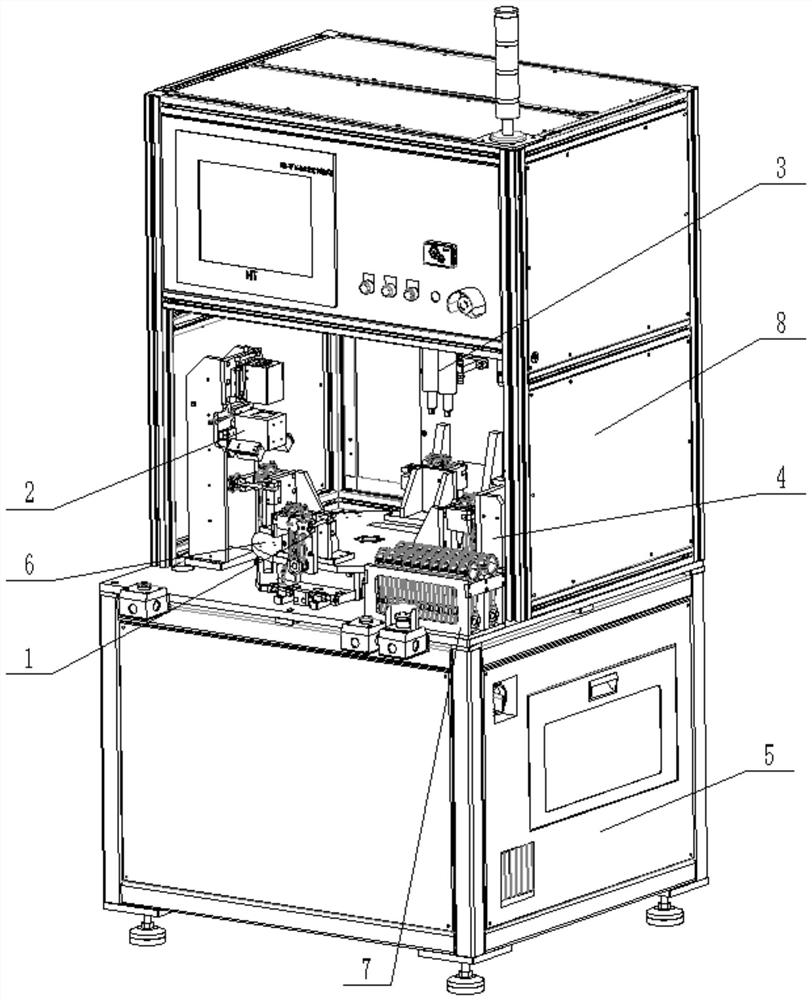
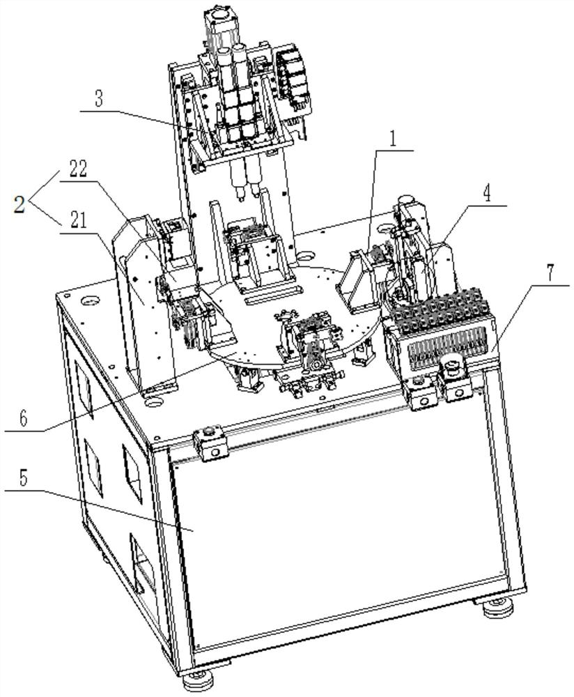
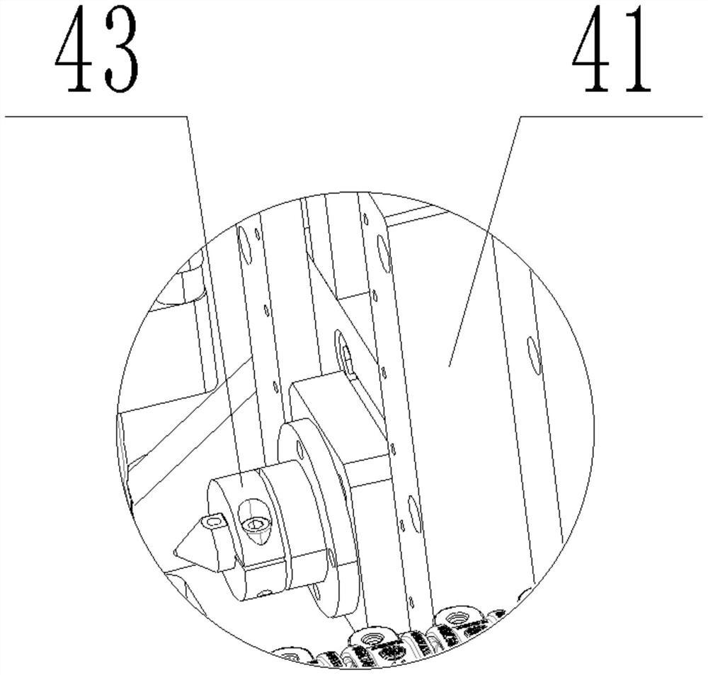
[0028] The present invention mainly includes a feeding installation structure 1, an identification mechanism 2, a screwing mechanism 3, and a marking mechanism 4, wherein the working principle of the screwing mechanism 3 is the prior art, but because the existing screwing mechanism 3 is simplex position, the present invention has made an improvement, using double stations to screw the screw, which is the innovation point of the present invention, and the combination of the above four to use the product to screw the product is also the innovation point of the present invention; the structure of the present invention will be done below Detailed elaboration.

[0029] First is the loading installation structure 1, the loading installation structure 1 includes a base plate 11 that plays a supporting role, a support plate 12 arranged above the base plate 11, a fixed block 13 arranged on the support plate 12, and a support plate that leans against the support plate. 12, the backing p...


PUM


Abstract

The invention discloses automatic screw locking marking equipment. The equipment comprises a feeding mounting structure, a recognition mechanism, a screw turning mechanism and a marking mechanism; a supporting platform is arranged below the recognition mechanism, the screw turning mechanism and the marking mechanism, a rotating mechanism is arranged below the feeding mounting structure, and the recognition mechanism, the screw turning mechanism and the marking mechanism are arranged on the outer circumference of the rotating mechanism; and the screw turning mechanism comprises a supporting column, a first electric cylinder installed on the supporting column, a first push rod connected with the first electric cylinder, a moving plate connected with the first push rod and a double-station screw turning device connected with the moving plate. The automatic screw locking marking equipment has the beneficial effects that through the combination of the feeding mounting structure, the recognition mechanism, the screw turning mechanism and the marking mechanism, feeding, mounting, recognizing, screw turning and marking of products can be well completed, use is convenient and fast, and themanual participation degree is low.

Description

technical field [0001] The invention relates to the technical field of screw locking equipment, in particular to an automatic screw locking marking equipment. Background technique [0002] Screws are indispensable fastening parts in daily life and industrial production, and are widely used in daily life and industrial production; such as electronic products, engineering machinery, furniture products, etc. [0003] With the advancement of science, automatic screwing equipment is used in the production and processing automatic production line instead of manually using manual screwdrivers or electric screwdrivers to fix and install products with screws. Although the efficiency has improved, the automatic screwing equipment currently on the market can only lock Screws, it is impossible to mark whether the product has been locked or not, and the existing equipment can only lock the screws one by one, that is, single-station work, but it is necessary for one product to be on the s...

Claims


Application Information

Patent Timeline
Patent Type & Authority Applications(China)
IPC IPC(8): B23P19/06
CPCB23P19/06
Inventor 罗宿程先锋陈国平蔡林虎付子卓
Owner SUZHOU TONGJIN PRECISION IND
Learn More