Supercooling pipe and air conditioning unit

A subcooling and tube body technology, applied in the direction of subcoolers, refrigerators, refrigeration components, etc., can solve the problems of limited increase in heat transfer area and large thermal resistance

Pending Publication Date: 2020-11-17
GREE ELECTRIC APPLIANCES INC
View PDF0 Cites 0 Cited by
  • Summary
  • Abstract
  • Description
  • Claims
  • Application Information

AI Technical Summary

Problems solved by technology

[0005] The embodiment of the present invention provides a subcooling tube and an air-conditioning unit to solve the technical probl

Method used


Image

  • Supercooling pipe and air conditioning unit
  • Supercooling pipe and air conditioning unit
  • Supercooling pipe and air conditioning unit

Examples


Embodiment Construction

[0030] In order to make the objectives, technical solutions, and advantages of the present invention clearer, the following further describes the present invention in detail with reference to the embodiments and the drawings. Here, the exemplary embodiments of the present invention and the description thereof are used to explain the present invention, but not as a limitation to the present invention.

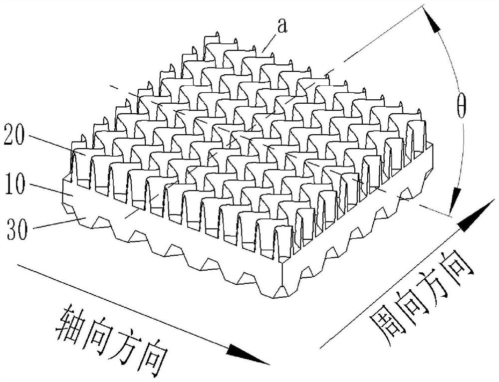
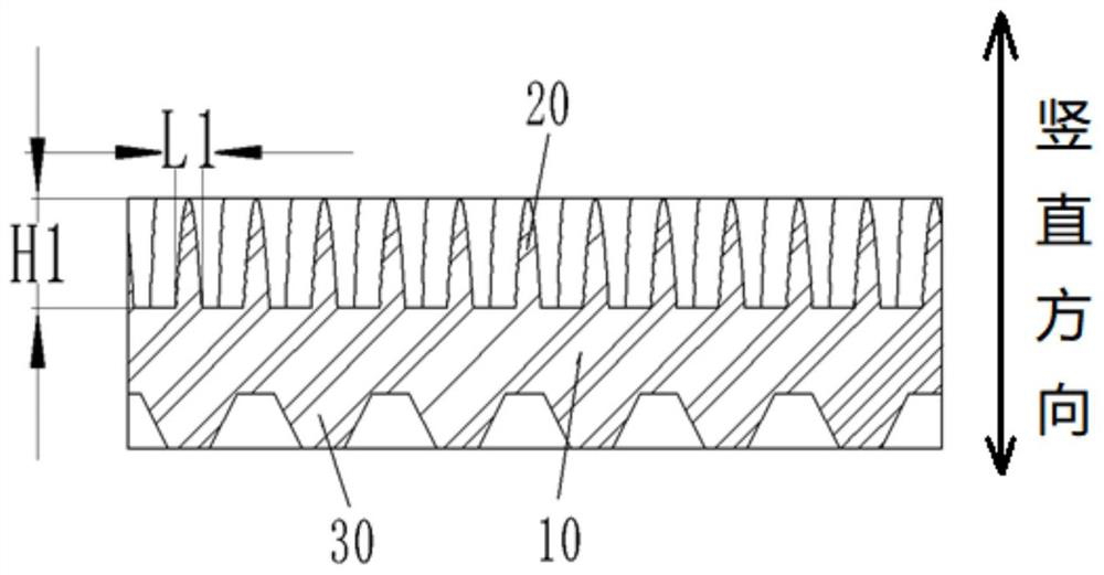
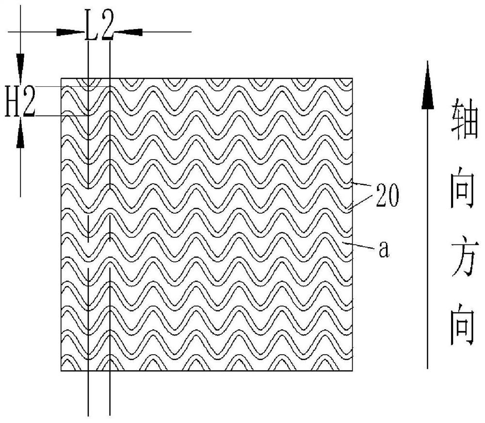
[0031] In order to solve the technical problem that the heat exchange area of ​​the supercooling tube in the prior art is limited in ways to increase and there is a large thermal resistance. Such as figure 1 As shown, in the technical solution of this embodiment, the supercooling tube includes a tube body 10 and a plurality of fins 20 arranged on the outer surface of the tube body 10, and the fins 20 are arranged in a wave shape along the length direction thereof. An undulating channel a is formed between two adjacent fins 20.

[0032] Applying the technical solution of the present ...


PUM

PropertyMeasurementUnit
Thicknessaaaaaaaaaa

Abstract

The invention provides a supercooling pipe and an air conditioning unit. The supercooling pipe comprises a pipe body and a plurality of fins arranged on the outer surface of the pipe body, wherein thefins are arranged in a wavy shape in the length direction, and a wavy channel is formed between every two adjacent fins. According to the technical scheme, on one hand, the heat exchange area of thefins is increased by arranging the fins in the wavy shape; and on the other hand, the wavy channel is formed between every two adjacent fins, and a refrigerant can be repeatedly baffled and disturbedby wavy structures when flowing through the wavy channels, so that the fluid disturbance strength is continuously enhanced, boundary layers on the fins are damaged to lower thermal resistance, the refrigerant can flow in the wavy channels to strengthen heat exchange, and heat is conducted away in time.

Description

Technical field [0001] The invention relates to the technical field of air conditioning equipment, and in particular to a supercooling pipe and an air conditioning unit. Background technique [0002] In central air-conditioning water-cooled horizontal condensers, in order to further improve the energy efficiency of the unit, a built-in supercooling structure is often installed at the bottom of the condenser. Among the existing supercooling structures, baffle, immersion, and flashing structures are currently widely used supercooling structures. In the baffled supercooling structure, the inside of the heat exchange tube is the cooling water, and the outside of the tube is the liquid refrigerant that baffles and flows under the action of the baffle. During the flow of the refrigerant, the heat is transferred to the cooling water in the tube through the tube wall to achieve The purpose of reducing the temperature of the refrigerant and increasing the degree of subcooling. [0003] In...

Claims


Application Information

Patent Timeline
IPC IPC(8): F28F1/42F25B40/02F24F1/0067F24F1/0325F24F1/18
CPCF24F1/18F25B40/02F28F1/422F24F1/0067F24F1/0325
Inventor 张治平王小勇胡东兵胡海利
Owner GREE ELECTRIC APPLIANCES INC
Why Eureka
Try Eureka