Pulse current generation method for battery testing

A pulse current and battery testing technology, which is applied to the parts of electrical measuring instruments, the improvement of basic electrical components, and the measurement of electricity. state accuracy, precise amplitude control, and precise pulse time control

Active Publication Date: 2020-11-17
苏州万瑞达电气有限公司
View PDF9 Cites 2 Cited by
  • Summary
  • Abstract
  • Description
  • Claims
  • Application Information

AI Technical Summary

Problems solved by technology

[0003] However, there are certain deficiencies in the existing ones that need to be improved. First, the existing battery pulse current test topology can be seen in Figure 4 , the electronic load is directly connected to the battery. If you want to generate a pulse current, you need to control the voltage VLoad of the electronic load, so that VLoad quickly drops and rises to form a voltage difference with VBat, thereby generating current. The rising and falling slopes of this pulse current are controlled by the electronic load. Influenced by the speed, the speed is relatively slow; secondly, when the current scheme performs pulse discharge test on the battery, the rising and falling slopes of the pulse current are not large enough. Using a load that cannot be fed back, the electric energy of the battery is consumed during the pulse test, and cannot be fed back to the grid, wasting electric energy

Method used


Image

  • Pulse current generation method for battery testing
  • Pulse current generation method for battery testing
  • Pulse current generation method for battery testing

Examples


Embodiment Construction

[0035] In order to make the technical means, creative features, goals and effects achieved by the present invention easy to understand, the present invention will be further described below in conjunction with specific embodiments.

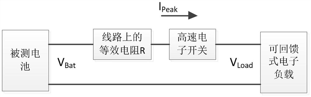
[0036] Such as Figure 1-4 As shown, a pulse current generation method for battery testing, the method specifically includes the following steps:

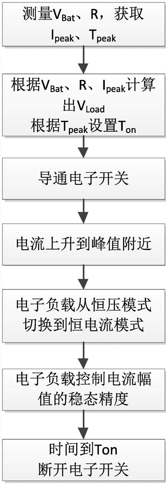
[0037] Step 1: Measure VBat, R, obtain Ipeak, Tpeak;

[0038] Step 2: Calculate Vload according to VBat, R, and Ipeak, and set Ton according to Tpeak;

[0039] Step 3: turn on the high-speed electronic switch;

[0040] Step 4: The current rises to near the peak value;

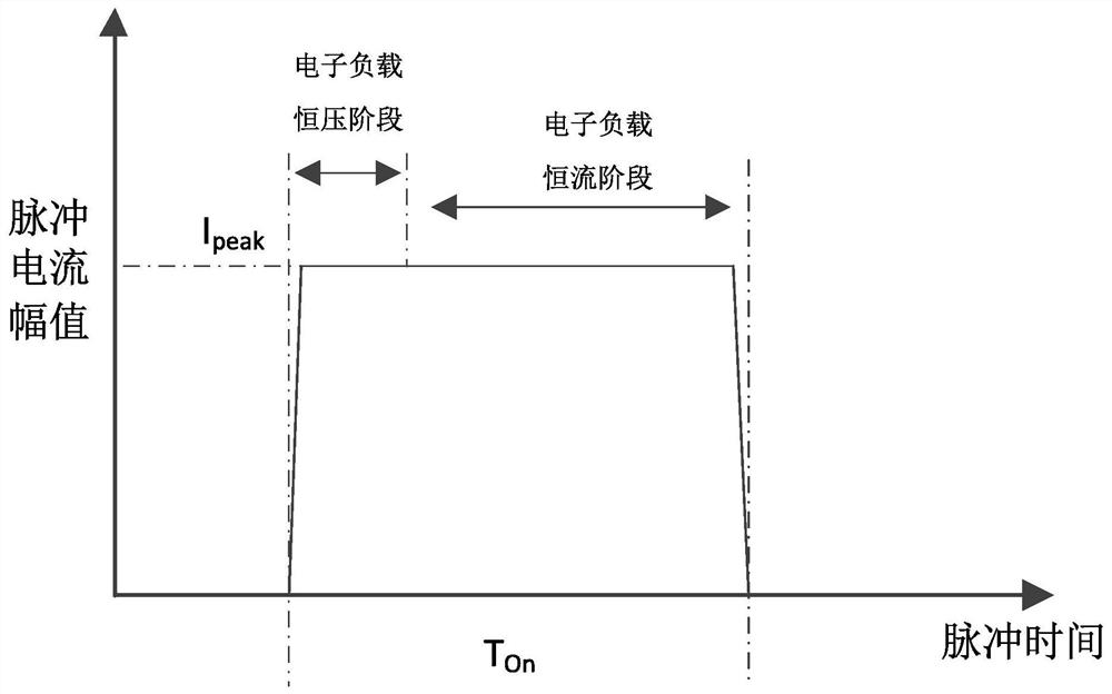
[0041] Step 5: The electronic load switches from constant voltage mode to constant current mode;

[0042] Step 6: The electronic load controls the steady-state accuracy of the current amplitude;

[0043] Step 7: Turn off the electronic switch when the time is up to Ton;

[0044] The measured battery voltage is VBat, the regenerati...


PUM


Abstract

The invention discloses a pulse current generation method for battery testing, which specifically comprises the following steps of: measuring VBat and R, acquiring Ipeak and Tpeak, calculating Vload according to the VBat, R and Ipeak; according to Tpeak, setting Ton, switching a high-speed electronic switch on, enabling current to rise to a position near a peak value, enabling an electronic load to be switched from a constant-voltage mode to a constant-current mode, enabling the electronic load to control steady-state precision and time of a current amplitude to the Ton to switch off the electronic switch, whereinthe voltage of a tested battery is VBat, the voltage of a feedback type electronic load is VLoad, and equivalent resistance on a line is R, and mosfet or IGBT is generally selected as the high-speed electronic switch. According to the pulse current generation method for the battery test, the ascending and descending time of the pulse current can be shorter, the ascending and descending slope of the current is larger, the pulse time control is more accurate, the amplitude control of the current pulse can be more accurate, the energy during the pulse test can be fed back tothe power grid, and the electric energy is not wasted.

Description

technical field [0001] The invention relates to the field of pulse current generation, in particular to a pulse current generation method for battery testing. Background technique [0002] Various lithium batteries, lead-acid batteries, hydrogen fuel cells, etc. are widely used in production and life. In the process of battery research and development and factory inspection, it is necessary to conduct a pulse current discharge test on the battery, that is, let the battery output a pulse current in a short time; [0003] However, there are certain deficiencies in the existing ones that need to be improved. First of all, the existing battery pulse current test topology can be seen in Figure 4 , the electronic load is directly connected to the battery. If you want to generate a pulse current, you need to control the voltage VLoad of the electronic load, so that VLoad quickly drops and rises to form a voltage difference with VBat, thereby generating current. The rising and falli...

Claims


Application Information

Patent Timeline
Patent Type & Authority Applications(China)
IPC IPC(8): G01R31/385G01R1/20G01R1/28
CPCG01R31/385G01R1/28G01R1/20G01R1/206Y02E60/10
Inventor 房振东
Owner 苏州万瑞达电气有限公司
Why Eureka
Try Eureka