
Grid zero-crossing compensation method

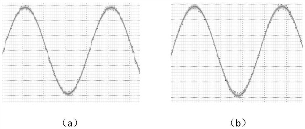
A power grid and zero-crossing technology, applied to electrical components, AC networks to reduce harmonics/ripples, output power conversion devices, etc., can solve problems that affect the quality of power grid current, current distortion, etc., to improve the problem and improve the process The effect of zero point distortion and reducing the total harmonic distortion rate

Active Publication Date: 2022-05-03
EAST GRP CO LTD
View PDF7 Cites 0 Cited by
  • Summary
  • Abstract
  • Description
  • Claims
  • Application Information

AI Technical Summary

Problems solved by technology

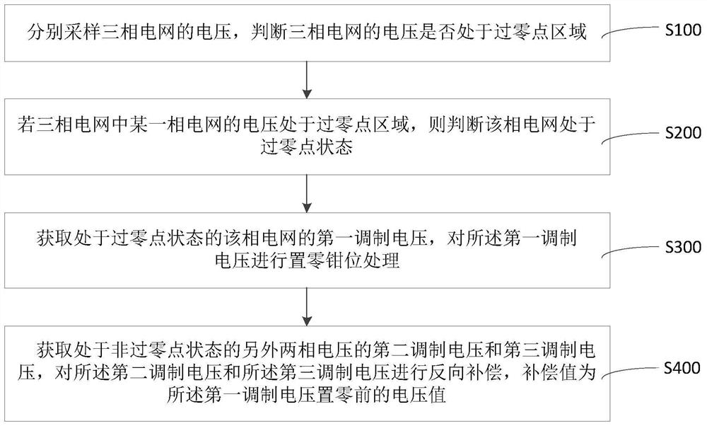
[0003] Based on this, it is necessary to provide a grid zero-crossing compensation method for the problem that current distortion is formed at the zero-crossing point of the grid and affects the current quality of the grid.

Method used


Image

  • Grid zero-crossing compensation method
  • Grid zero-crossing compensation method
  • Grid zero-crossing compensation method

Examples


Embodiment Construction

[0024] In order to facilitate the understanding of the present invention, the present invention will be described more fully below with reference to the associated drawings. Preferred embodiments of the invention are shown in the drawings. However, the present invention can be embodied in many different forms and is not limited to the embodiments described herein. On the contrary, the purpose of providing these embodiments is to make the disclosure of the present invention more thorough and comprehensive.

[0025] It should be noted that when an element is referred to as being “fixed” to another element, it can be directly on the other element or there can also be an intervening element. When an element is referred to as being "connected to" another element, it can be directly connected to the other element or intervening elements may also be present. As used herein, the terms "vertical", "horizontal", "left", "right", "upper", "lower", "front", "rear", "circumferential" and...


PUM


Abstract

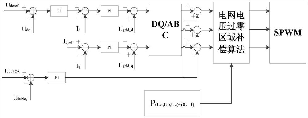
The invention relates to the technical field of rectifier converters, and discloses a zero-crossing compensation method for a power grid. In the above method, on the basis of the traditional voltage outer loop controlling the bus voltage and the current inner loop controlling the inductor current, the voltage judgment of the zero-crossing area of ​​the three-phase power grid is added. By collecting the voltage of the three-phase grid, it is judged whether the voltage of the three-phase grid is in the zero-crossing area to determine whether the three-phase grid is zero-crossing. When it is judged that any phase grid in the three-phase grid is zero-crossing, record the first modulation voltage of the phase grid and clamp the first modulation voltage to zero, and at the same time, the second modulation voltage of the other non-zero-crossing two-phase grid The modulation voltage and the third modulation voltage reversely compensate the voltage value of the first modulation voltage recorded before the zero setting. By compensating the three-phase grid at the zero-crossing point, it can solve the problem that the grid-side current lags behind the grid-side voltage due to the internal resistance of the boost inductor itself and the delay of the inductor current control signal in the hardware circuit, and improve the current quality.

Description

technical field [0001] The invention relates to the technical field of rectifier converters, in particular to a zero-crossing compensation method for a power grid. Background technique [0002] As a three-level rectifier, the three-phase Vienna rectifier is widely used in communication power supply, uninterruptible power supply, wind power generation and other occasions. Compared with the traditional two-level rectifier, it has higher power density, so it can reduce the volume and make the product lighter when applied in the product; in addition, its unique structure makes the stress of the switch tube half of the DC side bus voltage, so It is more suitable for use in high-power and high-voltage output, and it avoids the problem of bridge arm through-through, and at the same time avoids the problem of current quality deterioration caused by setting dead time, and indirectly improves its reliability. In the conventional control method of the three-phase Vienna rectifier, whe...

Claims


Application Information

Patent Timeline
Patent Type & Authority Patents(China)
IPC IPC(8): H02J3/01H02M1/12H02M7/12H02M1/08H02M1/06
CPCH02J3/01H02M1/12H02M7/12H02M1/08H02M1/083H02M1/06Y02E40/40
Inventor 聂欢高钢张凯涛
Owner EAST GRP CO LTD
Learn More