Compensation control method for input filtering capacitive current of CRM Boost PFC converter

A technology of input filtering and capacitive current, applied in the field of compensation control, can solve problems such as zero-crossing distortion of input current

Inactive Publication Date: 2018-10-23
NANJING UNIV OF AERONAUTICS & ASTRONAUTICS
View PDF4 Cites 4 Cited by
  • Summary
  • Abstract
  • Description
  • Claims
  • Application Information

AI Technical Summary

Problems solved by technology

[0004] The present invention aims at the problem of zero-crossing distortion of the input current caused by the input filter capaci

Method used


Image

  • Compensation control method for input filtering capacitive current of CRM Boost PFC converter
  • Compensation control method for input filtering capacitive current of CRM Boost PFC converter
  • Compensation control method for input filtering capacitive current of CRM Boost PFC converter

Examples


Embodiment 1

[0064] Embodiment 1: Based on the TMS320F28335 digital controller and variable on-time control, a digital control method for implementing input filter capacitor current compensation for a CRM Boost PFC converter using a freewheeling diode

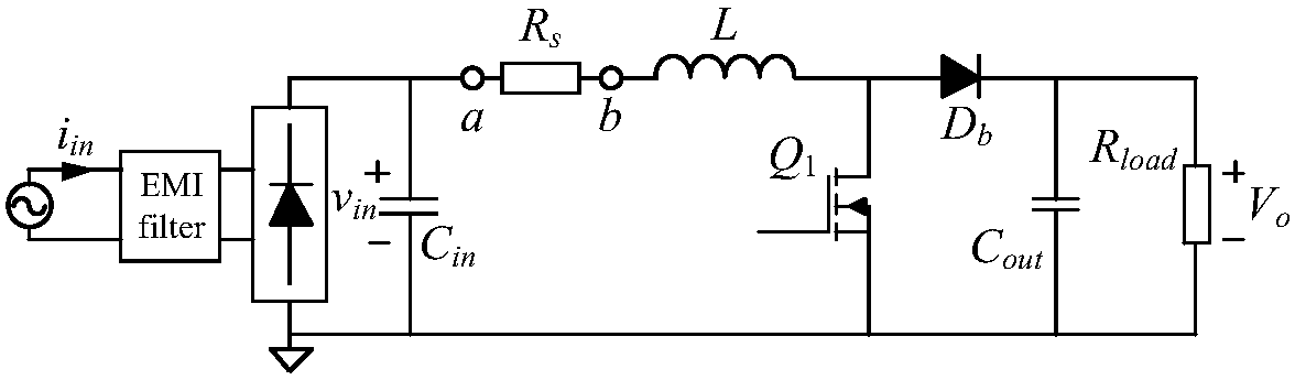
[0065] figure 1 It is the main circuit of CRM Boost PFC converter using freewheeling diode, including EMI filter, rectifier bridge, input filter capacitor, boost inductor, main switch tube, freewheeling diode, output filter capacitor and load.

[0066] The circuit parameters of the CRM Boost PFC converter used in the example are: boost inductance L=240μH, input filter capacitor capacitance C in = 100nF. The test conditions are: line frequency 50Hz, AC input voltage 110V and 220V, output bus voltage 400V, full load output power 200W.

[0067] In this experiment, whether the input current THD of compensation control is used or not is tested under the conditions of 20%, 40%, 50%, 60%, 80% and 100% load rate respectively.

[0068] image 3 ...

Embodiment 2

[0086] Embodiment 2: Based on the TMS320F28335 digital controller and constant on-time control, a digital control method for implementing input filter capacitor current compensation for a CRM Boost PFC converter using a synchronous rectification switch tube

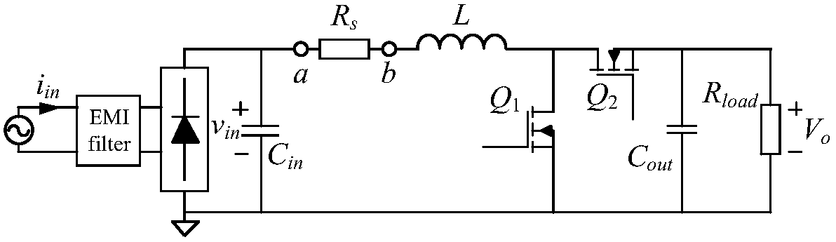
[0087] figure 2 The main circuit of the CRM Boost PFC converter using a synchronous rectification switch tube includes an EMI filter, a rectifier bridge, an input filter capacitor, a boost inductor, a main switch tube, a synchronous rectification switch tube, an output filter capacitor and a load.

[0088] The circuit parameters of the CRM Boost PFC converter used in the example are: boost inductance L=240μH, input filter capacitor capacitance C in = 100nF. The test conditions are: line frequency 50Hz, AC input voltage 110V and 220V, output bus voltage 400V, full load output power 200W.

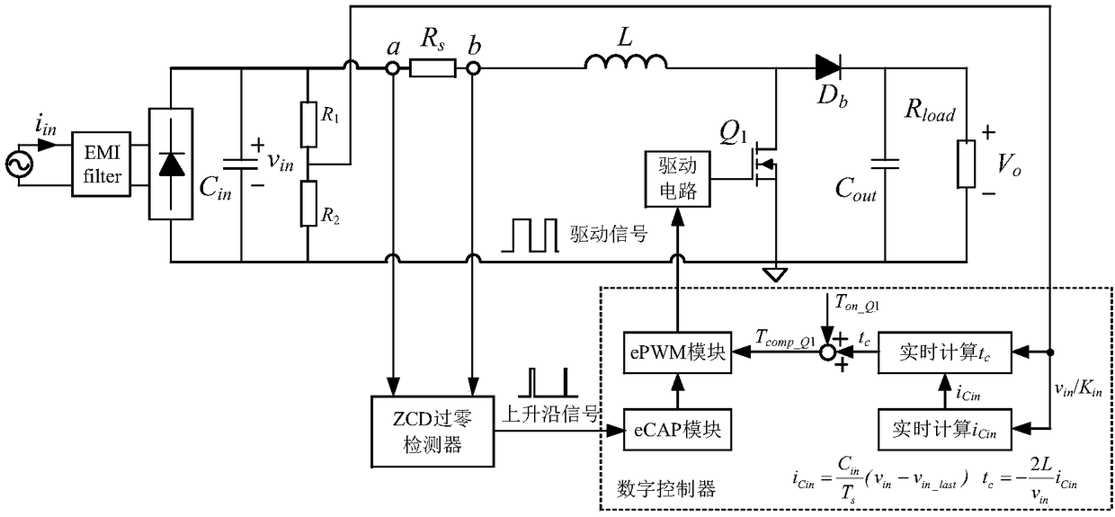
[0089] Figure 4 In order to realize the digital control circuit of compensation control for the CRM Boost PFC converter using sync...


PUM


Abstract

The invention discloses a compensation control method for an input filtering capacitive current of a CRM Boost PFC converter, belongs to the field of AC-DC power conversion, and aims at solving the problem that the input filtering capacitance tends to cause distortion of the input current in a traditional control method. Instant values of input and output voltages are sampled, the input filteringcapacitive current i<Cin> is calculated in real time, compensation time t<c> corresponding to a condition that a freewheeling diode is used in a main circuit and compensation time t<c> corresponding to a condition that a synchronizing rectification switch tube is used in the main circuit are calculated, conduction time of a power device is adjusted in real time to compensate the input filtering capacitive current, and the input current THD is reduced. The input filtering capacitive current is discretized on the basis of a digital controller, it is not required to establish a hardware circuit for detecting the input filtering capacitive current and the input voltage phase lock, and the circuit cost and the control difficulty are reduced greatly.

Description

technical field [0001] The invention belongs to the technical field of power converters, and in particular relates to a compensation control applied to an input filter capacitor current of a CRM Boost PFC converter. Background technique [0002] Power electronic devices have been widely used in fields such as electric vehicles, new energy, lighting, and portable electronic equipment, but their high-frequency switching characteristics also cause harmonic pollution problems in the power grid. In order to suppress harmonic content, improve power quality, and reduce input current THD, power factor correction technology (Power Factor Correction, PFC) has received more and more attention. The Boost PFC converter has the advantages of simple drive circuit design and small input current ripple, and has become the main topology of the active PFC converter. Among them, the CRM Boost PFC converter is widely used due to its small size, light weight, low cost and high power factor. [...

Claims


Application Information

Patent Timeline
IPC IPC(8): H02M7/217H02M1/42H02M1/12
CPCH02M1/12H02M1/4208H02M7/217H02M1/0003Y02B70/10
Inventor 吴羽任小永陈乾宏张之梁周玉婷
Owner NANJING UNIV OF AERONAUTICS & ASTRONAUTICS
Why Eureka
Try Eureka