

Sensor relay device and sensor relay system
A relay device and relay system technology, applied in transmission systems, signal transmission systems, radio transmission systems, etc., can solve the problems of increased overhead time and reduced transmission data rate, and achieve the goal of reducing overhead time and suppressing the transmission data rate Reduced effect
- Summary
- Abstract
- Description
- Claims
- Application Information
AI Technical Summary
Problems solved by technology
Method used
Image

Examples
no. 1 example
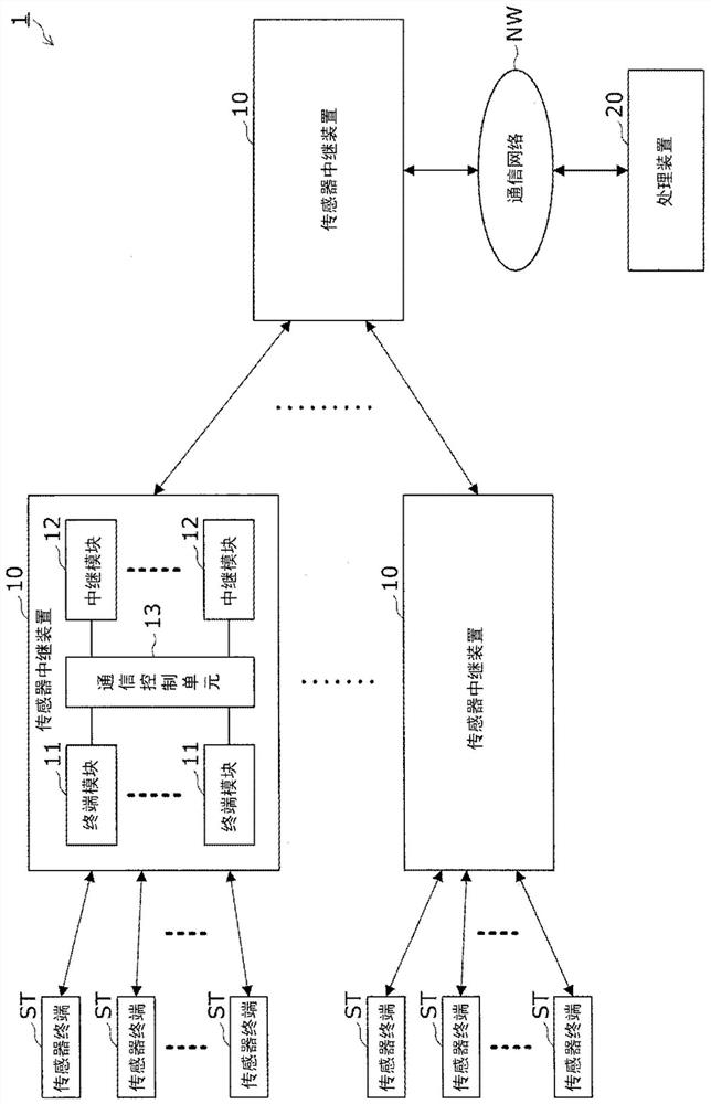
[0031] First, refer to figure 1 A sensor relay system 1 according to a first embodiment of the present invention is described.
[0032] A sensor relay system 1 includes a plurality of sensor terminals ST and a sensor relay device 10 for collecting various sensor data, for example, safety data acquired from buildings and facilities through sensor devices, wearable sensor Biometric information and the like detected on the human body, the sensor relay device 10 receives sensor data detected in the target object by the sensor terminal ST from the sensor terminal ST, and transmits the received data to the processing device 20 via the communication network NW.
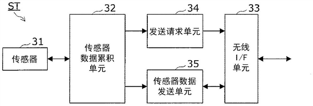
[0033] The sensor terminal ST includes a sensor terminal having a relatively low sensing function such as a temperature sensor and an acceleration sensor and a sensor terminal having a relatively high sensing function such as a camera for capturing moving images and still images.
[0034] The processing device 20 is genera...
no. 2 example
[0088] Next, a sensor relay device 10 according to a second embodiment of the present invention will be described.
[0089] The first embodiment exemplifies the case where the communication control unit 13 of the sensor relay device 10 performs a transmission permission / inhibition determination operation related to sensor data. The second embodiment will describe a case where each sensor terminal ST performs transmission permission / inhibition determination related to sensor data.
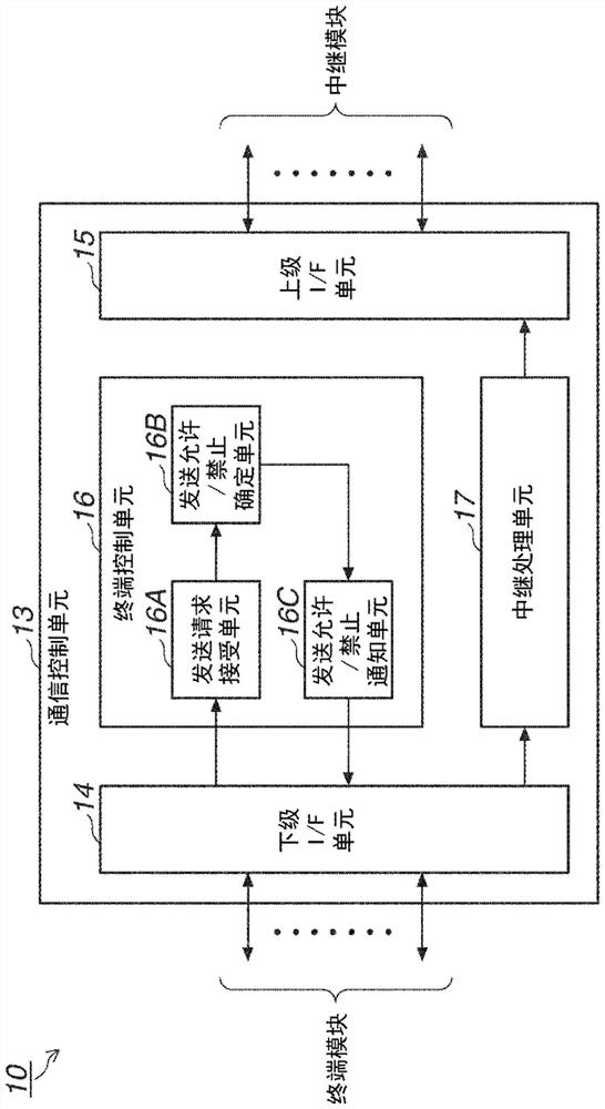
[0090] That is, in this example, if Figure 7 As shown, the communication control unit 13 includes a threshold notification unit 16D instead of a transmission request acceptance unit 16A, a transmission permission / inhibition determination unit 16B, and a transmission permission / inhibition notification unit 16C.
[0091] The threshold notification unit 16D has a function of notifying the sensor terminal ST under its control of a preset determination threshold via the lower I / F unit 14, and causing t...
no. 3 example
[0111] Next, a sensor relay system 1 according to a third embodiment of the present invention will be described.
[0112] The first embodiment describes the case where a plurality of sensor data are transmitted together from the sensor terminal ST to the sensor relay device 10 . This embodiment will describe a case where a plurality of sensor data are relayed and transmitted together from the sensor relay device 10 to a master device such as another sensor relay device 10 or the processing device 20 .
[0113] That is, in this embodiment, the communication control unit 13 of the sensor relay device 10 has a function of continuously relaying and transmitting the sensor data received from the sensor terminal ST when relaying and transmitting the sensor data received from the sensor terminal ST to the master device. A plurality of sensor data relayed and transmitted based on the same relay communication method among the sensor data. Note that other components related to the sens...
PUM
 Abstract
Description
Claims
Application Information