
Processing method for air vent on display panel

A processing method and technology of exhaust holes, which are applied in exhaust sealing, metal processing equipment, electric tube/lamp exhaust, etc., can solve the problems of glass substrate damage, cracks, damage, etc.

Inactive Publication Date: 2008-04-02
POONG SAN SYST
View PDF0 Cites 4 Cited by
  • Summary
  • Abstract
  • Description
  • Claims
  • Application Information

AI Technical Summary

Problems solved by technology

[0004] In the past, most of the vent holes were machined by diamond mechanical drilling. However, this processing method that directly contacts the glass substrate is not precise enough, and the vibration generated may damage the glass substrate and form a hole in the vent hole processing part. Burr (burr), and the formation of burr can cause cracks and breakage during heat treatment in the PDP manufacturing process
[0005] In addition, when the air vent is formed by mechanical drilling, a lot of glass powder dust will be generated, which not only deteriorates the working environment, but also requires a washing process, which makes it difficult to realize the enlargement of the display panel and the introduction of multi-faceted method.

Method used


Image

  • Processing method for air vent on display panel
  • Processing method for air vent on display panel
  • Processing method for air vent on display panel

Examples


Embodiment Construction

[0018] Embodiments of the present invention will be described in detail below with reference to the accompanying drawings.

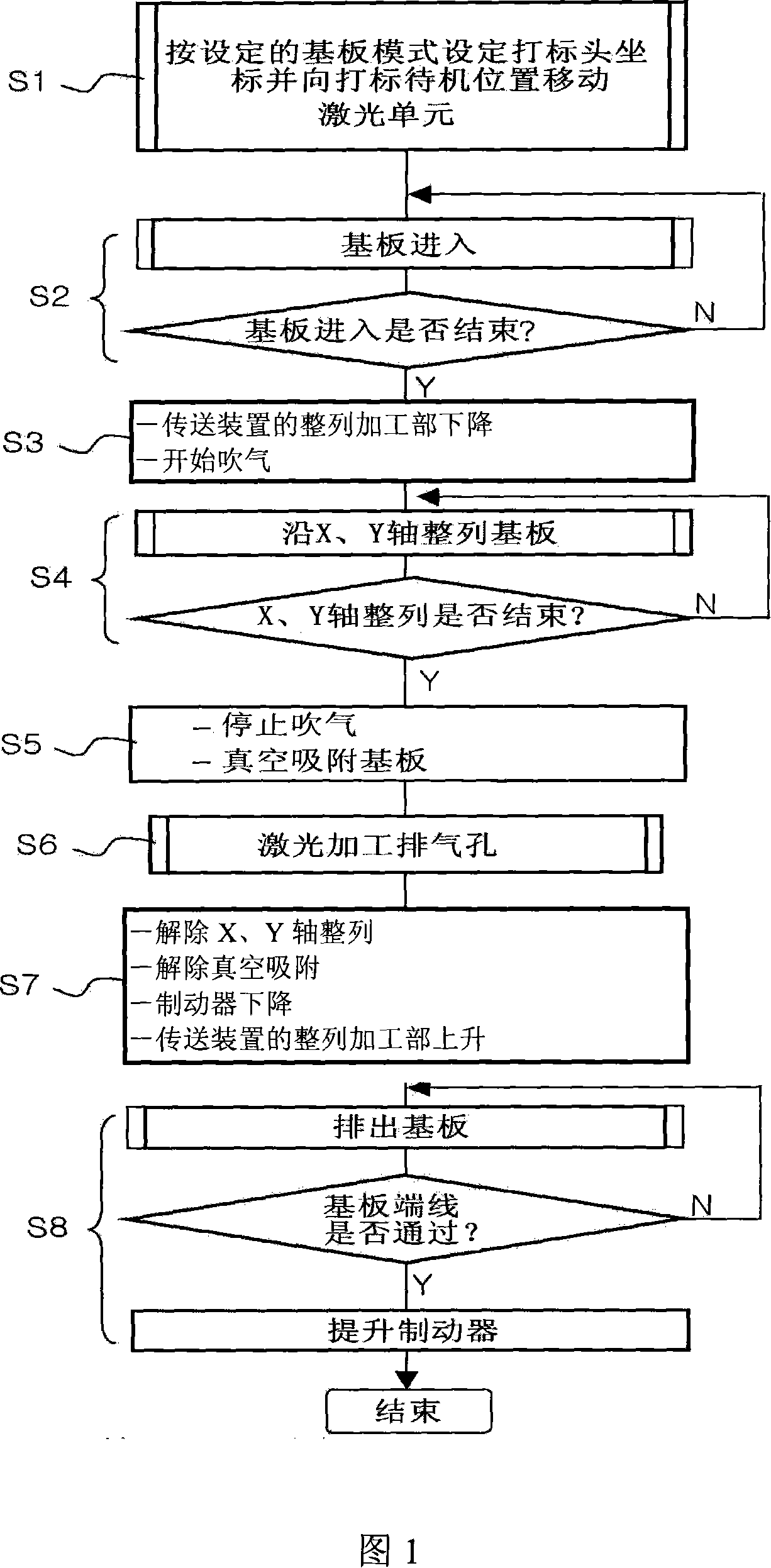
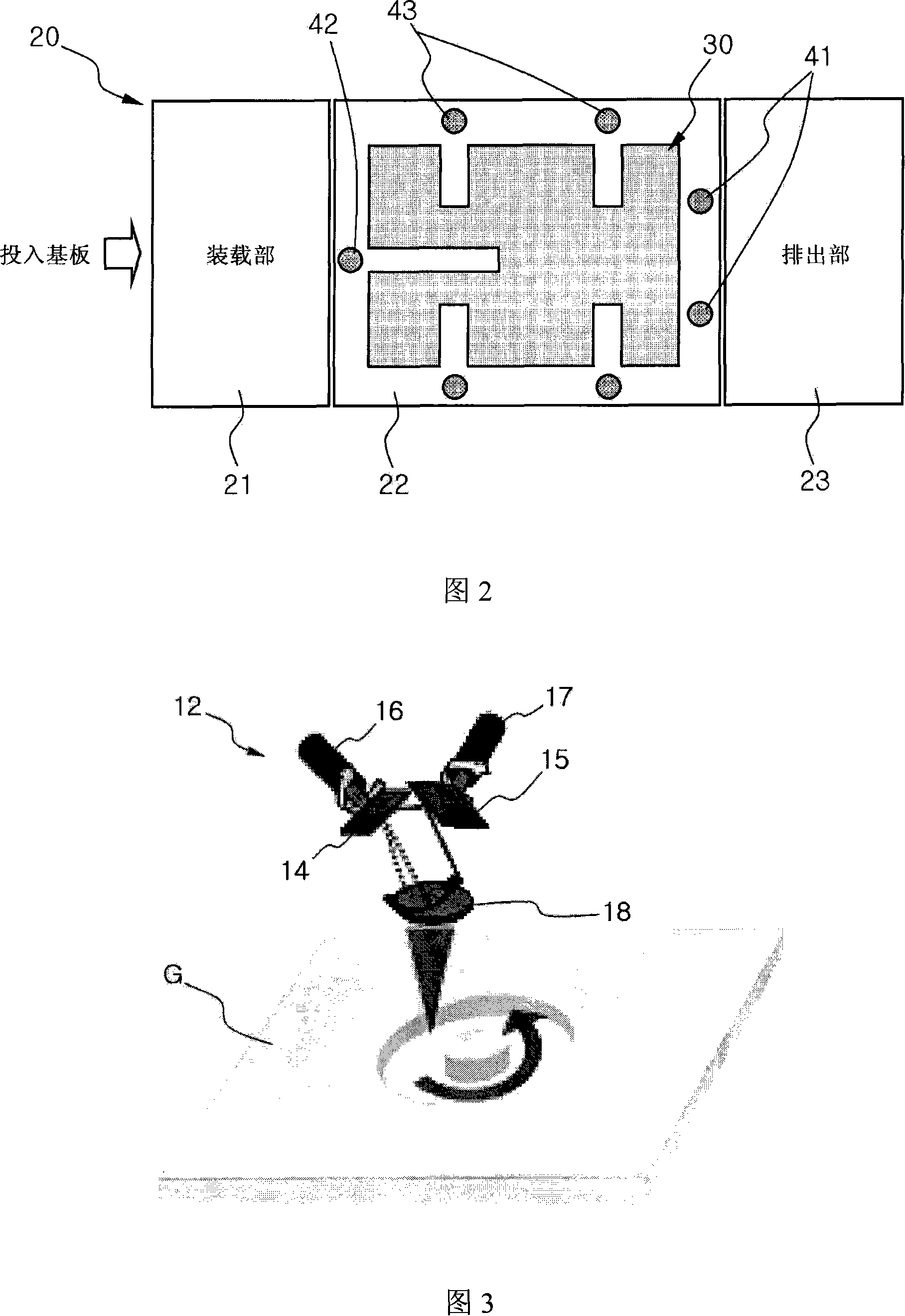
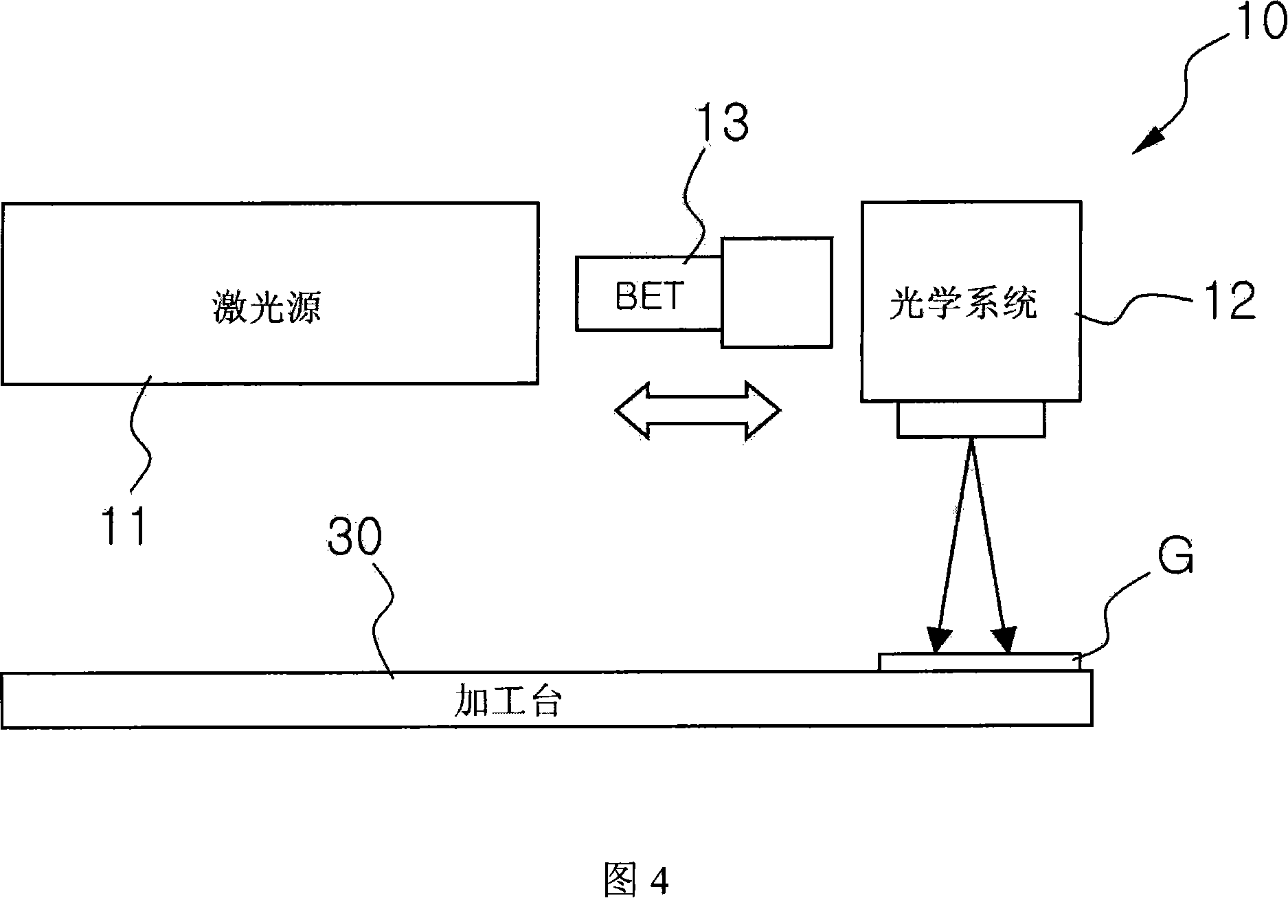
[0019] Fig. 1 is a flow chart of the method for processing the vent hole of the display panel according to the present invention, Fig. 2 is a schematic diagram of the device used in the method of processing the vent hole of the display panel according to the present invention, and Fig. 3 is a schematic diagram of laser processing of the substrate according to the present invention , FIG. 4 is a schematic diagram of adjusting the Z-axis direction during laser processing in the present invention.

[0020] As shown in FIG. 1 and FIG. 2 , the method for processing the vent holes of the display panel according to the present invention processes the vent holes in a non-contact manner by irradiating the focused laser beam from the laser unit 10 to the two-dimensional plane of the substrate G. The method includes: step S1, setting the marking head coordinates of...


PUM


Abstract

A processing method of a display panel exhaust hole comprises: setting a mark printing head coordinate of a laser unit and moving the laser unit to the mark printing stand-by position; loading the substrate on the transmission device composed of loading portion, an arranging processing portion and an exhaust portion, and judging whether the substrate entering into a processing table configured onthe arranging processing portion; descending the arranging processing portion to release the contact with the substrate when confirming the substrate enters into the processing table, meanwhile, floating the substrate; arranging the floating substrate to the center of the processing table and judging whether the central arranging of the substrate is finished; releasing the floating state of the substrate after stopping the central arranging of the substrate, fixing the substrate on the processing table by the vacuum adsorption; starting the dust collecting portion to collect the dust when illuminating the laser to the processing position of the substrate through the laser unit to process the exhaust hole; releasing the vacuum adsorption to the substrate after finishing the processing of the exhaust hole, driving the arranging processing portion to raise so as to make the substrate contact with the transmission device; exhausting the substrate through the transmission device and judgingwhether the substrate base line is passed.

Description

technical field [0001] The present invention relates to a method for processing air vents on a display panel, in particular to non-contact processing using a laser, thereby improving the processing efficiency of the air vents, and at the same time eliminating substrate friction when aligning the substrates. method. Background technique [0002] Generally speaking, PDP (Plasma Display Panel) is the panel of the display part of the plasma display device. Gases such as neon gas are sealed in the gap between two thin glass substrates, and the inner surface of the glass substrate is horizontally The transparent electrodes are arranged in the direction and the vertical direction. [0003] In the manufacturing process of the above-mentioned PDP, when two glass substrates are bonded, it is necessary to process an exhaust hole in one of the glass substrates in advance in order to discharge the gas remaining inside. [0004] In the past, most of the vent holes were machined by diamo...

Claims


Application Information

Patent Timeline
IPC IPC(8): H01J9/46H01J9/24H01J9/385H01J9/00B23K26/38B23K26/04B23K26/42C03B21/04H01J11/34H01J11/46H01J11/48H01J17/16
CPCB23K26/382H01J9/24H01J9/241H01J9/385H01J9/46H01J11/34H01J2217/49264
Inventor 郑玧秀
Owner POONG SAN SYST
Learn More