
Method for controlling at least one radial fan in refrigeration plant and radial fan

A refrigeration equipment, radial flow technology, applied to the components of the pumping device for elastic fluid, pump control, mechanical equipment, etc., can solve the problem of radial fan overload, damage, not making full use of the operating area, etc. , to achieve the effect of complete prosecution and monitoring

Active Publication Date: 2020-11-17
TEQTONIQ GMBH
View PDF12 Cites 0 Cited by
  • Summary
  • Abstract
  • Description
  • Claims
  • Application Information

AI Technical Summary

Problems solved by technology

Or it may happen that the radial fan is overloaded and thus damaged, or the operating area is not optimally utilized

Method used


Image

  • Method for controlling at least one radial fan in refrigeration plant and radial fan
  • Method for controlling at least one radial fan in refrigeration plant and radial fan
  • Method for controlling at least one radial fan in refrigeration plant and radial fan

Examples


Embodiment Construction

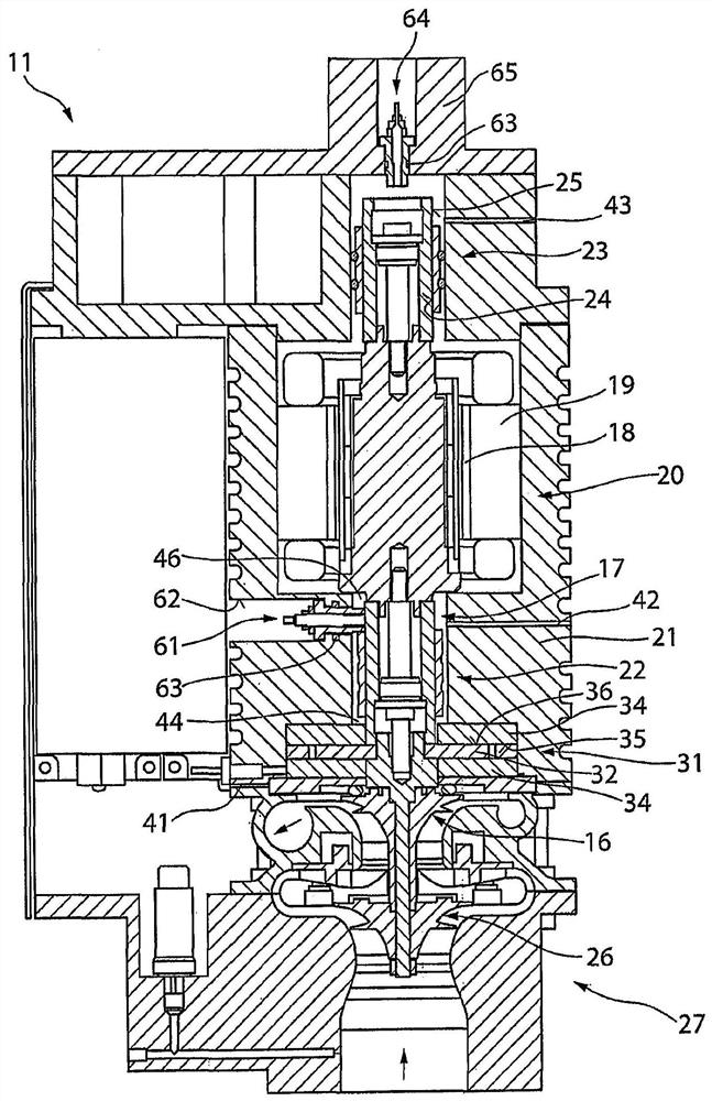
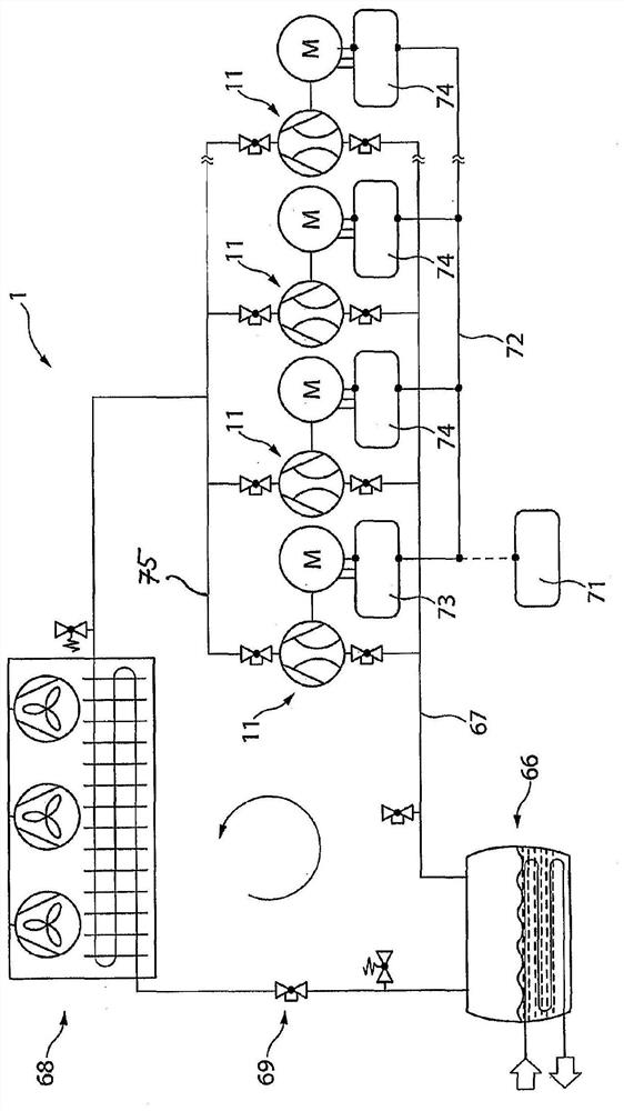
[0023] exist figure 1 , a schematic cross-sectional view of a radial fan 11 is shown. Via the radial fan 11 , the refrigerant is accelerated radially by at least one impeller 16 , 26 of the compressor 27 and deflected into the circuit of the refrigeration plant 1 , for example in image 3 shown in .

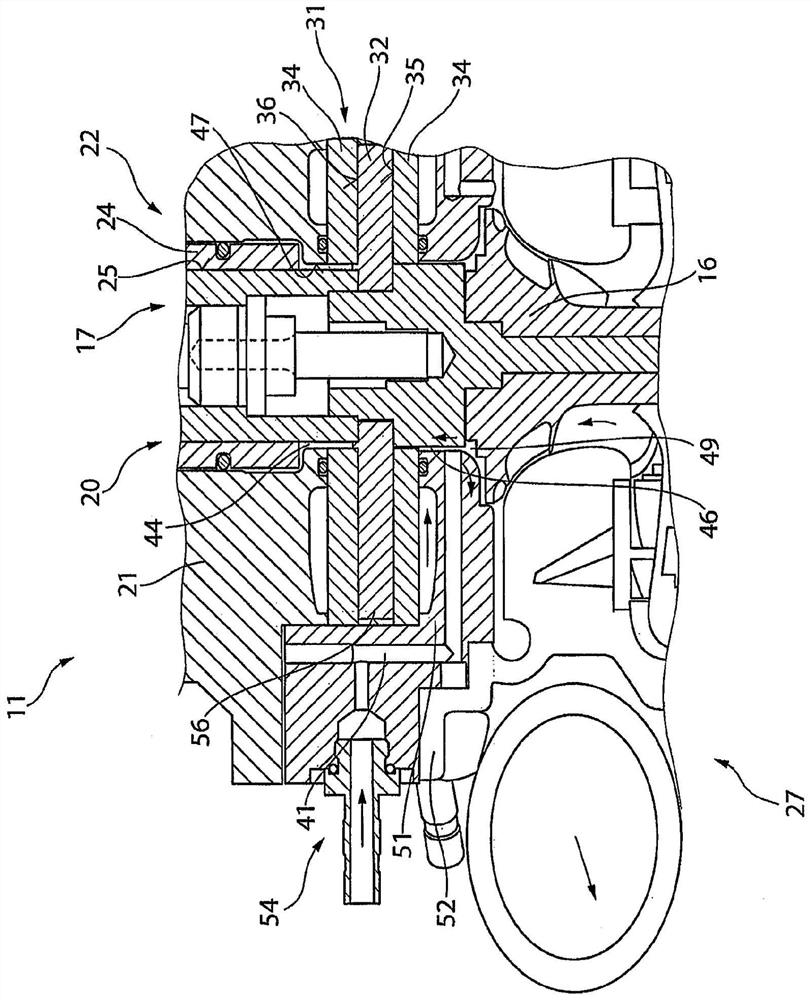
[0024] Via the radial fan 11 , the cooling medium is accelerated radially by at least one impeller 16 , 26 of the compressor 27 and guided compressed into the gas pressure line 75 on the compression side of the refrigeration device 1 ( image 3 ). The impellers 16 , 26 are located on a shaft 17 which is driven by a motor 20 in the central region of the motor housing 21 . The motor 20 consists of a rotor 18 connected to a shaft 17 and a stator 19 fastened to a motor housing 21 . The area arranged outside the impellers 16 , 26 as viewed from the shaft 17 forms the pressure side of the blower. Radial bearings 22 , 23 , in particular a lower radial gas bearing 22 and an upper ra...


PUM


Abstract

The invention relates to a method for controlling at least one radial fan (11) in a refrigeration plant (1). In the method, the radial fan (11) comprises a housing (21) in which a shaft (17) is rotatably mounted, the shaft receives at least one impeller (16, 26) of a compressor (27) at one end, and the compressor is secured to the housing (21); the housing (21) comprises at least one radial bearing (22, 23) and at least one axial gas bearing (31), the shaft (17) is rotatably mounted in the housing (21) by means of the bearings, and the radial fan has a motor (20) which is driven by a rotor (18) and a stator (19) and drives the shaft (17), wherein an operating point of the shaft (17) is detected by means of at least one vibration meter (61, 64) associated with the shaft (17) and the operating point is transmitted to a control device (71) for ascertaining an operating state of the radial fan (11).

Description

technical field [0001] The invention relates to a method for controlling at least one radial fan in a refrigeration installation and to a refrigeration installation. Background technique [0002] A radial fan for a gas laser is known from DE 10 2010 001 538 A1. Such a radial fan comprises a motor consisting of a rotor and a stator between a first radial bearing and a second radial bearing, in particular a radial gas bearing. An impeller is arranged on a shaft driven by a motor in the housing of the radial fan to turn the laser gas of the laser assembly. The radial fan further comprises an axial gas bearing positioned away from the impeller, wherein the motor is positioned between the axial gas bearing and the second radial bearing with a first radial bearing arranged directly adjacent thereto. between the impellers. The pressure medium is fed to the radial gas bearing and the axial gas bearing through channels in the housing to form a hydrodynamic bearing. [0003] Such ...

Claims


Application Information

Patent Timeline
Patent Type & Authority Applications(China)
IPC IPC(8): F04D27/00F04D29/051F04D29/057
CPCF05D2270/334F04D27/001F04D29/0513F04D29/057F04D27/0269
Inventor A·莱尔M·比蒂科费尔D·穆里C·安布尔
Owner TEQTONIQ GMBH
Learn More