Centrifugal fan assembly production method and centrifugal fan assembly equipment

A technology for centrifugal fans and assembly equipment, applied in assembly machines, metal processing equipment, manufacturing tools, etc., can solve the problems of low degree of automation and low production efficiency

Inactive Publication Date: 2020-11-20
卢叶敏
View PDF0 Cites 4 Cited by
  • Summary
  • Abstract
  • Description
  • Claims
  • Application Information

AI Technical Summary

Problems solved by technology

[0004] The purpose of the present invention is to propose a centrifugal fan assembly and production method with efficient and orderly assembly process and high production efficiency and its production in view of the shortcomings of the centrifugal fan assembly integration and automation degree in the prior art, and the production efficiency is not high. equipment

Method used


Image

  • Centrifugal fan assembly production method and centrifugal fan assembly equipment
  • Centrifugal fan assembly production method and centrifugal fan assembly equipment
  • Centrifugal fan assembly production method and centrifugal fan assembly equipment

Examples


Embodiment Construction

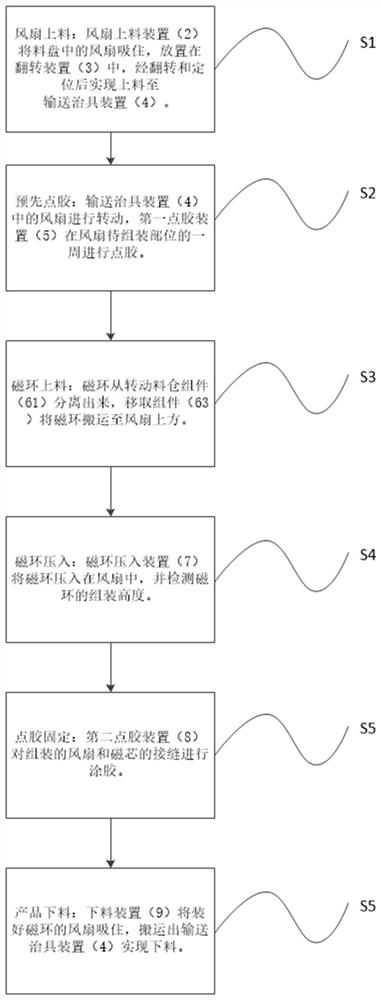
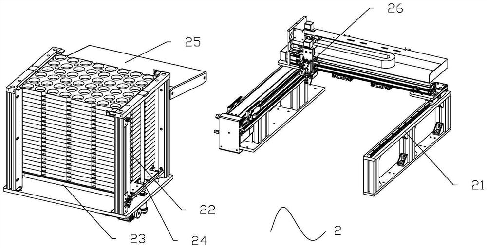
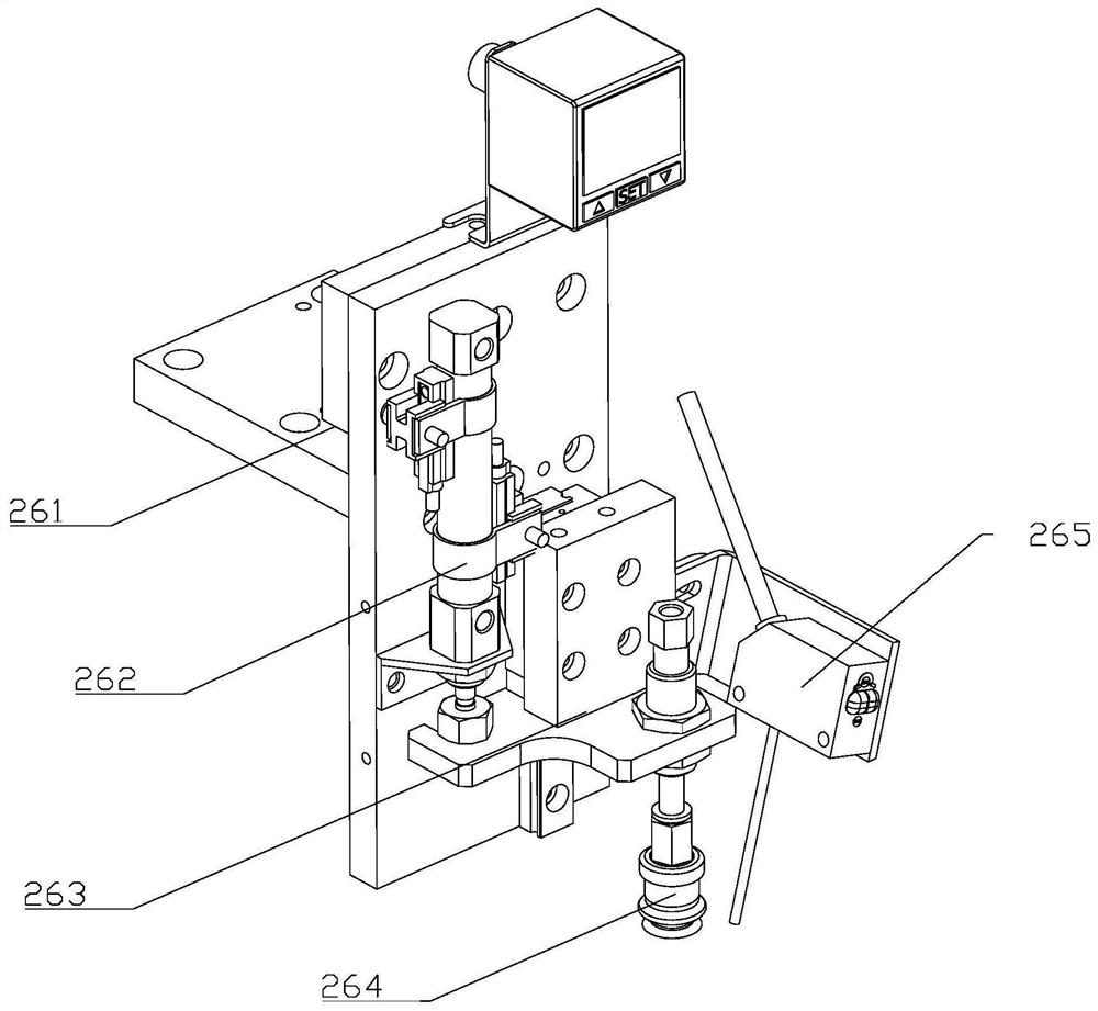
[0040] Such as Figure 2-12 As shown, a centrifugal fan assembly equipment includes a frame 1 and a wind wheel feeding device 2 arranged on the frame, a wind wheel turning device 3, a conveying jig device 4, a first dispensing device 5, and an annular magnetic coil Material device 6, annular magnetic coil press-in device 7, second dispensing device 8 and unloading device 9; described wind wheel feeding device 2 is connected with wind wheel turning device 3, and described wind wheel turning device 3 It is connected with the conveying fixture device 4; the conveying fixture device 4 is installed in the center of the frame 1, and the wind wheel turning device 3, the first glue dispensing device 5, the annular magnetic coil feeding device 6, and the annular magnetic coil are pressed into The device 7 , the second dispensing device 8 and the unloading device 9 are arranged around the outer periphery of the conveying jig device 4 in sequence.

[0041] The wind wheel feeding device ...


PUM


Abstract

The invention discloses centrifugal fan assembly equipment. The centrifugal fan assembly equipment includes a rack, and a wind wheel feeding device, a wind wheel turning device, a conveying jig device, a first glue dispensing device, an annular magnetic coil feeding device, an annular magnetic coil pressing device, a second glue dispensing device and a discharging device arranged on the rack; thewind wheel feeding device is connected to the wind wheel turning device; the wind wheel turning device is connected to the conveying jig device; the conveying jig device is installed in the center ofthe rack; and the wind wheel turning device, the first glue dispensing device, the annular magnetic coil feeding device, the annular magnetic coil pressing device, the second glue dispensing device and the discharging device are sequentially arranged around the outer circumference of the conveying jig device. The invention has the advantages of efficient and orderly connection of assembly processes and high production efficiency.

Description

technical field [0001] The invention relates to the technical field of fan production, in particular to a centrifugal fan assembly production method and production equipment thereof. Background technique [0002] Centrifugal fans are based on the principle of converting kinetic energy into potential energy, using high-speed rotating impellers to accelerate the gas, then decelerate, change the flow direction, and convert kinetic energy into potential energy. Centrifugal fans are widely used in ventilation, dust removal and cooling of factories, mines, tunnels, cooling towers, vehicles, ships and buildings; ventilation and induction of boilers and industrial furnaces; cooling and cooling of air conditioning equipment and household appliances ventilation. The centrifugal fan is composed of a wind wheel and an annular magnetic coil in the middle, and a coil stator is set in the annular magnetic coil to drive the wind wheel to rotate. [0003] The existing technology has the fo...

Claims


Application Information

Patent Timeline
Patent Type & Authority Applications(China)
IPC IPC(8): B23P21/00
CPCB23P21/006
Inventor 卢叶敏陈森林陈彦伟
Owner 卢叶敏
Why Eureka
Try Eureka