A Power Generation Buoy with Improved Structure

An improved structure, power generation technology, applied in buoys, ocean energy power generation, engine components, etc., can solve problems such as increased buoy power consumption, power generation device damage, lamp buoy tilt, etc., to improve the ability to resist wind and waves, and improve stability. , the effect of reducing the rotation speed

Active Publication Date: 2022-05-31
ZHEJIANG OCEAN UNIV
View PDF7 Cites 0 Cited by
  • Summary
  • Abstract
  • Description
  • Claims
  • Application Information

AI Technical Summary

Problems solved by technology

[0003] Buoy lights include four types: fixed light buoys, light buoys, light boats, and lighthouses. Light buoys are a kind of navigation mark that floats on the water surface and is anchored at a designated position. External factors such as external factors will cause the buoy to tilt and shake. The buoy lights of the existing cylindrical buoys are fixed by anchors. When the wind and waves are relatively large, the pull rope will be straightened directly, and the light buoy will tilt, which is not easy to be observed or scanned by radar. It is realized that when the wind and waves are severe, the buoy lights may shake a lot, or even overturn, directly destroying the buoy lights
[0004] In addition, because more electronic equipment is installed on the buoy, the power consumption of the buoy is increased. Therefore, power generation devices are usually installed on the buoy lights to generate power by using wave energy. However, when the wind and waves are strong, it is easy to cause damage to these power generation devices. destroy

Method used


Image

  • A Power Generation Buoy with Improved Structure
  • A Power Generation Buoy with Improved Structure
  • A Power Generation Buoy with Improved Structure

Examples


Embodiment Construction

[0059] The following are specific embodiments of the present invention and the accompanying drawings to further describe the technical solutions of the present invention, but the present invention is not limited to these embodiments.

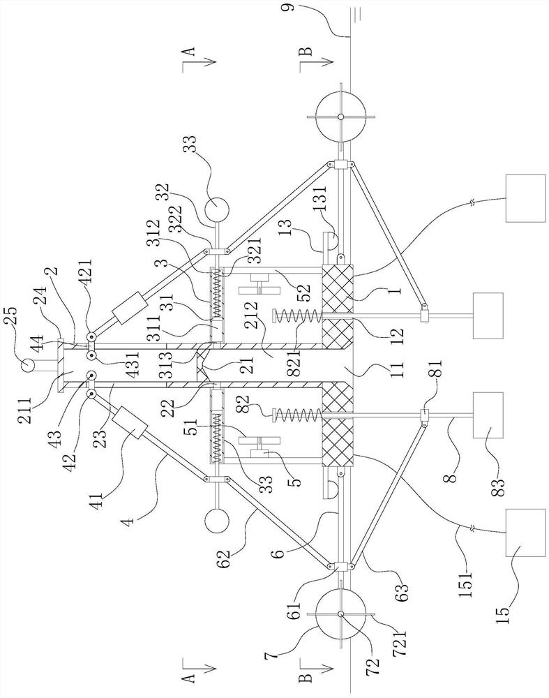
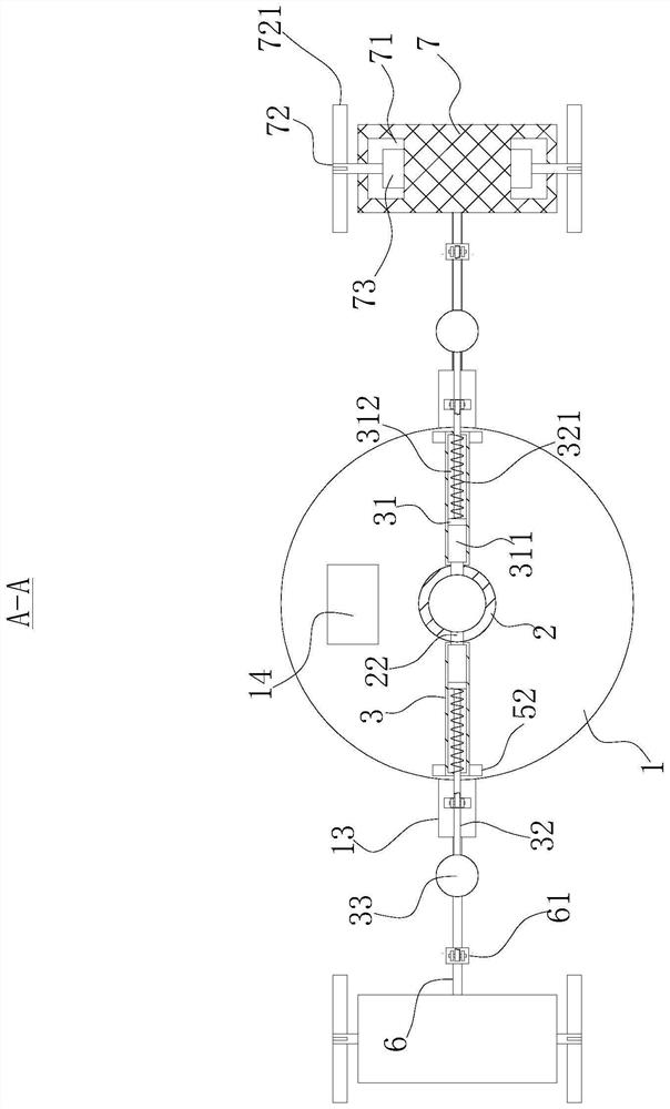
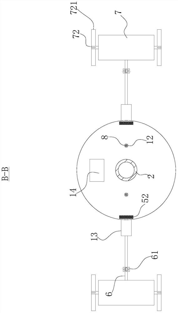
[0060] like Figures 1 to 4 As shown, a power generation buoy with an improved structure includes a floating body 1, a circular tube 2, a blocking block 21 and two adjustment devices.

[0061] The floating body 1 is provided with a first through hole 11 penetrating the upper and lower sides of the floating body 1 . Preferably, the lower end of the first through hole 11 is flared outward.

[0062] An anchor 15 is fastened to the lower side of the floating body 1 through a wire rope 151 , and the anchor 15 can limit the moving range of the floating body 1 , so that the floating body 1 is always close to the water surface 9 .

[0063] The circular tube 2 is vertically fixed on the upper side of the floating body 1 , and the first through hole 11 i...


PUM


Abstract

The invention provides a power generation buoy with an improved structure and belongs to the technical field of buoys. The present invention includes a floating body, a round pipe, a blocking block and two adjustment devices. The floating body is provided with a first perforation, and the round pipe is vertically fixed on the upper side of the floating body. In the round tube, the blocking block divides the inside of the round tube into an upper cavity and a lower cavity. Two adjustment devices are symmetrically arranged on both sides of the round tube. The adjustment device includes a rotating rod, a limit mechanism, a driving mechanism and an adjusting mechanism. The rotating rod One end of the buoy is hinged on the side of the buoy, and the other end is fixed with a buoy. Both ends of the buoy are equipped with a power generation mechanism. The power generation mechanism can use the impact of waves to generate electricity. The turning rod continues to rotate upwards, and the drive mechanism can drive the buoy to rotate downwards to below the water surface. When the buoy rotates downward, the adjustment mechanism can reduce the center of gravity of the buoy. The invention has strong wind and wave resistance.

Description

technical field [0001] The invention belongs to the technical field of buoys, and relates to a power generation buoy with an improved structure. Background technique [0002] The buoy light is a night luminous sign set on the shore or on the water to ensure the safe navigation of the ship at night. It emits the specified light color and flash frequency at night to achieve the specified illumination angle and visibility distance. [0003] The buoy light includes four types: fixed light beacon, light buoy, light boat and lighthouse. Light buoy is a kind of navigation beacon that floats on the water surface and is anchored at a designated position. External factors will cause the floating body to tilt and sway. The existing cylindrical floating body buoy lights are fixed by anchors. When the wind and waves are relatively large, the pull rope will be directly stretched, and the light buoy will be tilted, which is not easy to be observed or scanned by radar. When the wind and wa...

Claims


Application Information

Patent Timeline
Patent Type & Authority Patents(China)
IPC IPC(8): B63B22/00B63B22/04F03B13/14
CPCB63B22/00B63B22/04F03B13/14Y02E10/30
Inventor 蔡铭洁祝捍皓陈超黄江华薛洋洋崔志强苏峥段泽徐韩明研杨毅涛
Owner ZHEJIANG OCEAN UNIV
Why Eureka
Try Eureka