On-line Monitoring System of Blast Furnace Material Surface Shape
What is AI technical title?
AI technical title is built by Patsnap AI team. It summarizes the technical point description of the patent document.
A monitoring system, blast furnace material level technology, applied in inspection devices and other directions, can solve the problems of complex laser cooling equipment and high cooling costs
Active Publication Date: 2021-10-12
石家庄锦荣电子科技有限公司
View PDF8 Cites 0 Cited by
Summary
Abstract
Description
Claims
Application Information
AI Technical Summary
This helps you quickly interpret patents by identifying the three key elements:
Problems solved by technology
Method used
Benefits of technology
Problems solved by technology
[0003] The invention proposes an online monitoring system for the shape of the blast furnace material surface, which solves the problem of complex laser cooling equipment and high cooling costs
Method used
Image
Click on the blue label to locate the original text in one second.
Reading with bidirectional positioning of images and text.
Examples
Embodiment 1
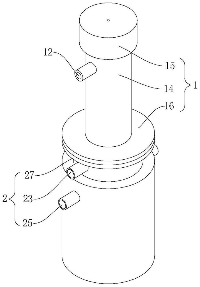
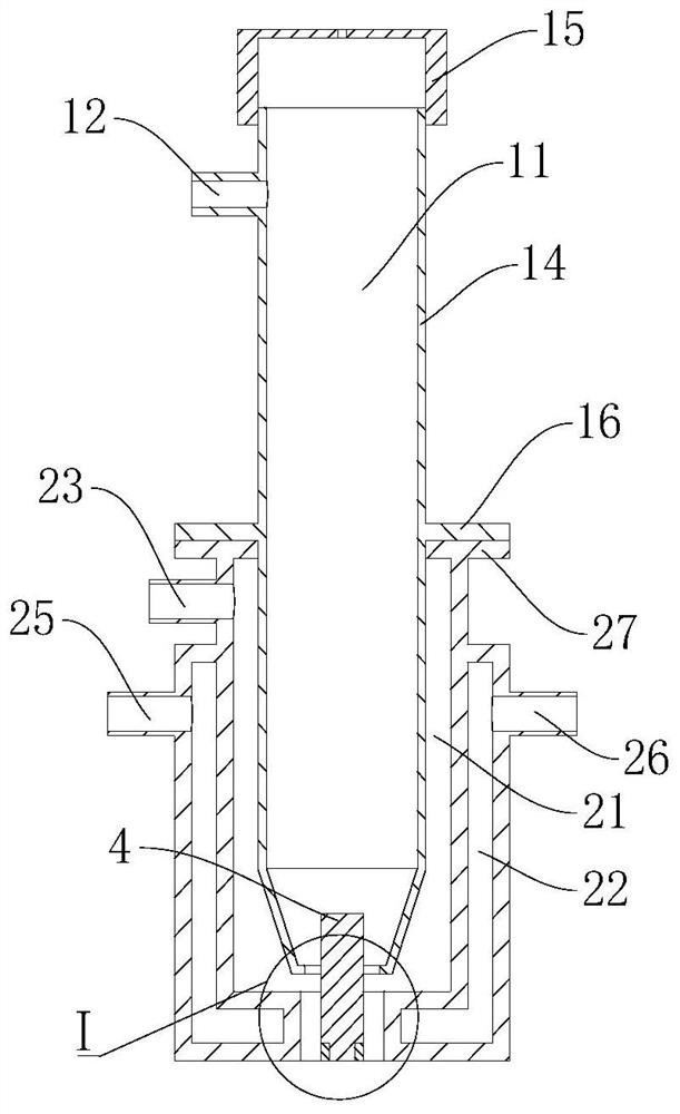
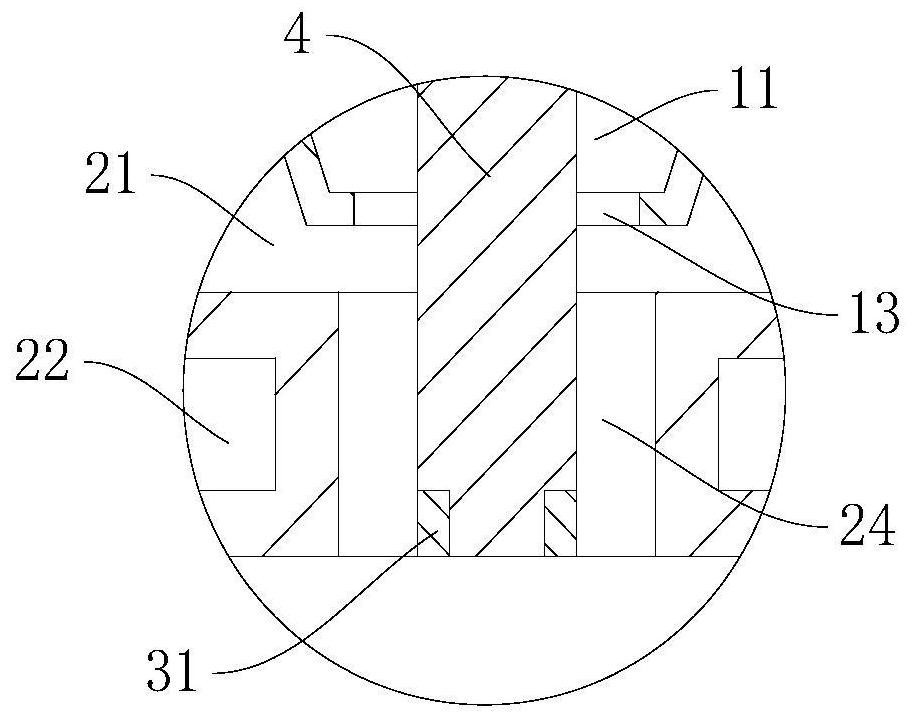
[0036] like Figure 1 ~ Figure 4 As shown, this embodiment proposes an online monitoring system for the shape of the blast furnace charge surface, including: a super-infrared laser scanning system, a digital camera system, a computer system, and a laser cooling system. It is characterized in that the laser cooling system includes:
[0037] The connecting body 1 has a first air chamber 11, a first air inlet 12 and a first air outlet 13, the first air inlet 12 and the first air outlet 13 communicate with the first air chamber 11 and form a first cooling air road;
[0038] The installation body 2 is connected with the connecting body 1. The installation body 2 has a second air chamber 21, a water chamber 22, a second air inlet 23, a second air outlet 24, a water inlet 25 and a water outlet 26, and the second air inlet 23 and the second air outlet 24 are in communication with the second air chamber 21 and form a second cooling air duct, the water inlet 25 and the water outlet 26 ...
Embodiment 2
[0059] like Figure 5 ~ Figure 7 As shown, the present embodiment also proposes the nozzle 5 and the absorbent cotton 6, the mounting body 2 is also provided with a water permeable hole 28, the water permeable hole 28 communicates with the second air chamber 21 and the water chamber 22, and the nozzle 5 is located at the water inlet 25 , the water permeable hole 28 is set opposite to the water outlet hole of the nozzle 5, and the absorbent cotton 6 is located in the second air chamber 21.
[0060] In this embodiment, a nozzle 5 is provided at the water inlet 25, a water-absorbent cotton 6 is provided in the second air chamber 21, and a water-permeable hole 28 is opened in the installation body 2, and the water-permeable hole 28 communicates with the second air chamber 21 and The water holding chamber 22, the water in the cooling water channel is sprayed into the water holding chamber 22 from the nozzle 5, and the water permeable hole 28 is arranged relative to the nozzle 5, so...
PUM
Property
Measurement
Unit
diameter
aaaaa
aaaaa
Abstract
The present invention relates to the technical field of ironmaking blast furnace visualization, and proposes an on-line monitoring system for the shape of blast furnace material surface, which includes a connecting body, a first air chamber, a first air inlet and a first air outlet, a first air inlet and a first The air outlets are all in communication with the first air chamber and form the first cooling air duct; the installation body is connected with the connecting body, and the installation body has a second air chamber, a water chamber, a second air inlet, a second air outlet, an inlet The water inlet and the water outlet, the second air inlet and the second air outlet are all connected with the second air chamber and form a second cooling air passage, the water inlet and the water outlet are both connected with the water chamber and form a cooling channel, and the water chamber is wrapped A part of the second air chamber, the first air outlet communicates with the second air chamber; the fixing frame is located at the second air outlet for fixing the laser, part of the laser is located in the first cooling air duct, and the other part is located in the second inside the cooling duct. Through the above technical solution, the problems of complex laser cooling equipment and high cooling cost are solved.
Description
technical field [0001] The invention relates to the technical field of ironmaking blast furnace visualization, in particular to an online monitoring system for the shape of a blast furnace material surface. Background technique [0002] In order to improve the efficiency of ironmaking, increase the output of steel, and solve the problem of visualization inside the ironmaking blast furnace under the harsh environment, an online monitoring system for the shape of the blast furnace material surface that can digitize the internal conditions of the blast furnace has been developed. The online monitoring system for the shape of the blast furnace material surface can obtain the precise surface shape of the ironmaking raw material in a radial direction in the ironmaking blast furnace in real time, and can obtain real-time displacement of the material surface, platform width, etc. through the surface shape of the raw material, which is a reference for blast furnace material distributi...
Claims
Application Information
Patent Timeline
Application Date:The date an application was filed.
Publication Date:The date a patent or application was officially published.
First Publication Date:The earliest publication date of a patent with the same application number.
Issue Date:Publication date of the patent grant document.
PCT Entry Date:The Entry date of PCT National Phase.
Estimated Expiry Date:The statutory expiry date of a patent right according to the Patent Law, and it is the longest term of protection that the patent right can achieve without the termination of the patent right due to other reasons(Term extension factor has been taken into account ).
Invalid Date:Actual expiry date is based on effective date or publication date of legal transaction data of invalid patent.

