Flow-limiting regulation device for drainage

A technology of regulating device and current limiting, which is applied in valve device, valve operation/release device, valve details, etc., can solve the problems such as troublesome operation, low regulation accuracy, single operation method, etc. The effect of simple operation and reduced maintenance cost

Inactive Publication Date: 2020-11-20
合肥翰骏环保技术开发有限公司
View PDF7 Cites 2 Cited by
  • Summary
  • Abstract
  • Description
  • Claims
  • Application Information

AI Technical Summary

Problems solved by technology

[0004] The purpose of the present invention is to provide a drainage current limiting adjustment device, through the meshing setting between the gear ring and the gear plate on the second current limiting mechanism, under the action of the forward and reverse rotation of the motor, the second current limiting mechanism can be driven Rotate, so as to realize the current limiting adjustment by changing the size of the gap between the fan-shaped plate and the fan-shaped through groove, through the meshing setting between the driving bevel gear and the driven bevel gear, the staff can manually control and change the fan-shaped plate by turning the handle The size of the gap between the fan-shaped channel and the fan-shaped channel realizes current-limiting adjustment. The flow rate of the water can be detected through the setting of the flow rate detection sensor. Through the setting of the display screen, the staff can intuitively understand the flow rate of the water, which is convenient for the staff to be more accurate. The adjustment solves the problems of troublesome operation, single operation mode, low adjustment accuracy and high maintenance cost of the existing current limiting adjustment device.

Method used


Image

  • Flow-limiting regulation device for drainage
  • Flow-limiting regulation device for drainage
  • Flow-limiting regulation device for drainage

Examples


Embodiment 1

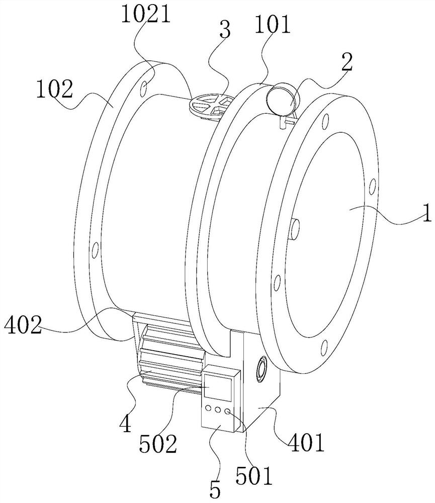
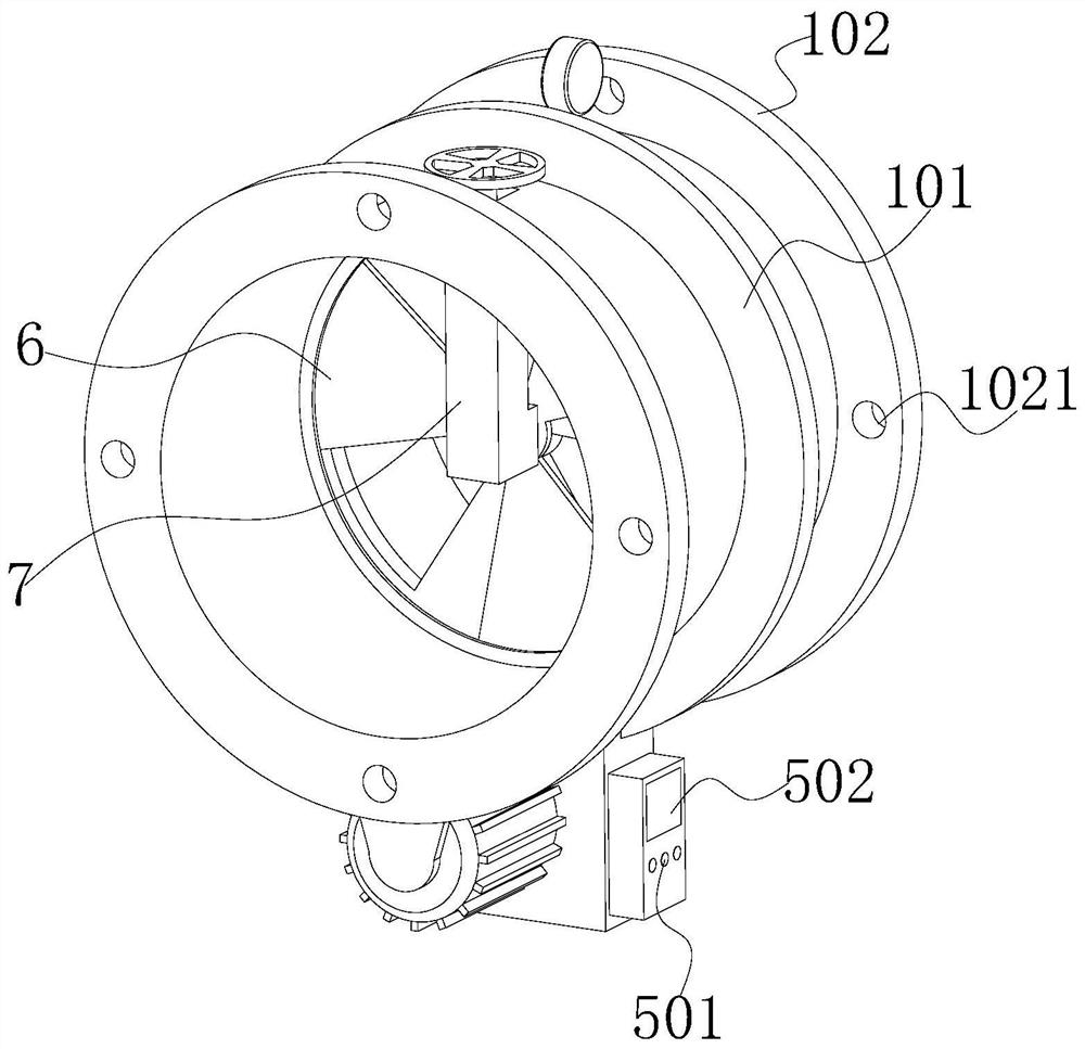
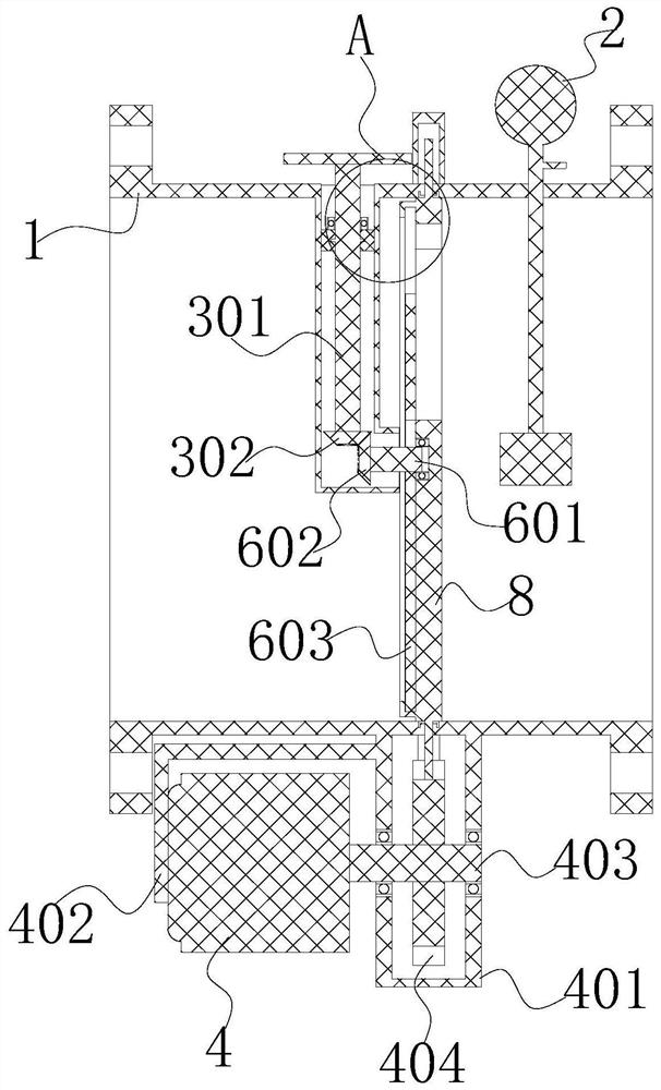
[0048] see Figure 1-3 As shown, the present invention is a drainage flow limiting adjustment device, comprising a pipe body 1, a first flow limiting mechanism 6 and a second flow limiting mechanism 8, the inside of the pipe body 1 is concentrically provided with a second flow limiting mechanism 8, the second flow limiting mechanism The pipe body 1 on one side of the flow limiting mechanism 8 is concentrically provided with a first flow limiting mechanism 6, and the cooperative arrangement of the first flow limiting mechanism 6 and the second flow limiting mechanism 8 can play the role of flow limiting, while the second flow limiting mechanism The inside of the pipe body 1 on the other side of the mechanism 8 is provided with a flow velocity detection sensor 2. The flow velocity detection sensor 2 is used to detect the water flow velocity at the water inlet end, and the flow velocity detection sensor 2 is fixedly socketed on the side wall of the pipe body 1;

[0049] Wherein, ...


PUM


Abstract

The invention discloses a flow-limiting regulation device for drainage, and relates to the technical field of flow limiting for drainage. The flow-limiting regulation device for drainage comprises a pipe body, a first flow-limiting mechanism and a second flow-limiting mechanism. The second flow-limiting mechanism is concentrically arranged in the pipe body. The first flow-limiting mechanism is concentrically arranged in the pipe body and is located on one side of the second flow-limiting mechanism. A flow velocity detection sensor is arranged in the pipe body, located on the other side of thesecond flow-limiting mechanism and fixedly connected to the side wall of the pipe body in a sleeving manner. Wherein, a circular through groove is concentrically formed in the pipe body outside the second flow-limiting mechanism in the circumferential direction. The first flow-limiting mechanism comprises a fan-shaped plate and a first disk. According to the flow-limiting regulation device for drainage, through the arrangement of the first flow-limiting mechanism, the second flow-limiting mechanism, a driving conical gear, a gear disk, a rotary handle, a single-chip microcomputer, the flow velocity detection sensor and a display screen and the manual cooperation of components, the flow-limiting regulation device is easy to operate in use, low in maintenance cost and high in regulation precision and has abundant regulation modes.

Description

technical field [0001] The invention belongs to the technical field of drainage and flow limitation, and in particular relates to a drainage and flow limitation adjustment device, which is mainly used for the role of flow limitation and regulation in the process of water transportation. Background technique [0002] In the existing social construction, whether it is the construction of water conservancy projects or the construction of urban water system distribution, it is necessary to use the flow-limiting adjustment device to regulate the flow of water transportation, the distribution of flow-limiting adjustment in the water system and the protection process of water pipes At present, most of the existing current-limiting adjustment devices use control valves to adjust manually. This adjustment method is troublesome to operate. After the single adjustment method is damaged, the adjustment mechanism needs to be replaced, which increases the The maintenance cost of the curre...

Claims


Application Information

Patent Timeline
Patent Type & Authority Applications(China)
IPC IPC(8): F16K3/08F16K3/314F16K27/04F16K31/04F16K31/53F16K37/00
CPCF16K3/0209F16K3/08F16K3/314F16K27/045F16K31/043F16K31/535F16K37/0091
Inventor 胡宗山
Owner 合肥翰骏环保技术开发有限公司
Why Eureka
Try Eureka