Car lamp with heat dissipation function

A technology of car lights and functions, which is applied in the direction of motor vehicles, road vehicles, vehicle parts, etc., can solve problems such as the temperature increase of car lights, achieve the effects of improving stability, facilitating quick maintenance, and improving performance

Inactive Publication Date: 2020-11-20
湖南德霸照明制造有限公司
View PDF1 Cites 1 Cited by
  • Summary
  • Abstract
  • Description
  • Claims
  • Application Information

AI Technical Summary

Problems solved by technology

The above-mentioned patents have the following disadvantages: the above-mentioned device uses the rotation of the motor to drive the fan blades to rotate, and dissipates heat by enhancing the circulation of the air. However, the motor will also generate heat during operation, which will increase the temperature of the car lights, which cannot meet people's requirements.

Method used


Image

  • Car lamp with heat dissipation function
  • Car lamp with heat dissipation function
  • Car lamp with heat dissipation function

Examples


Embodiment 1

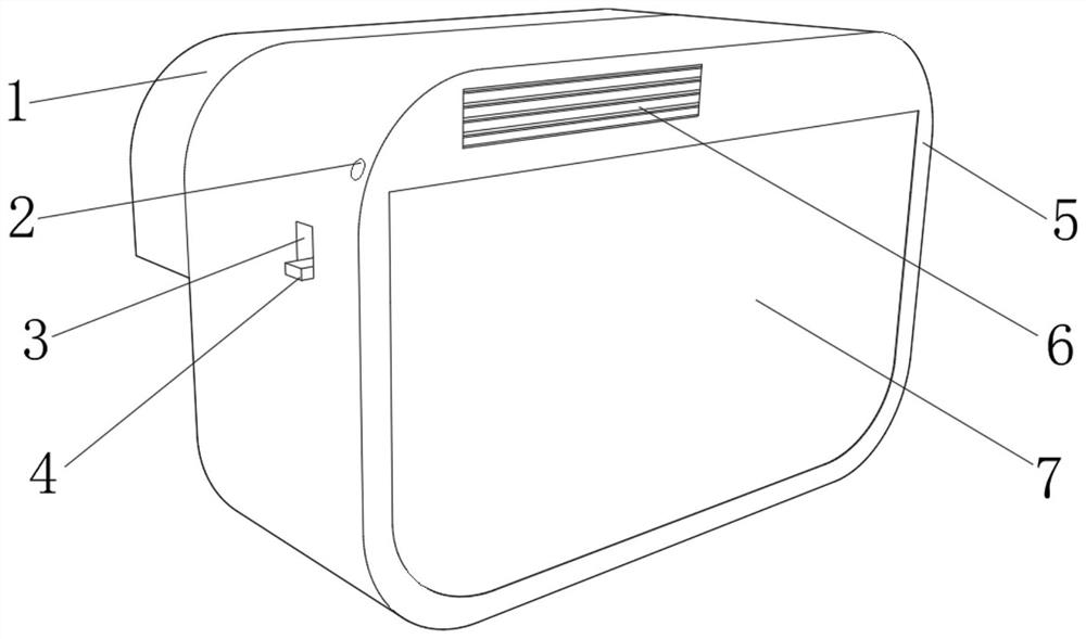
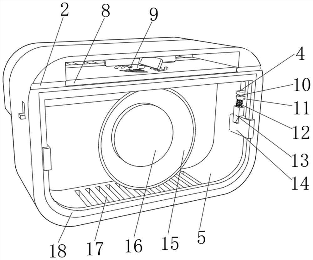
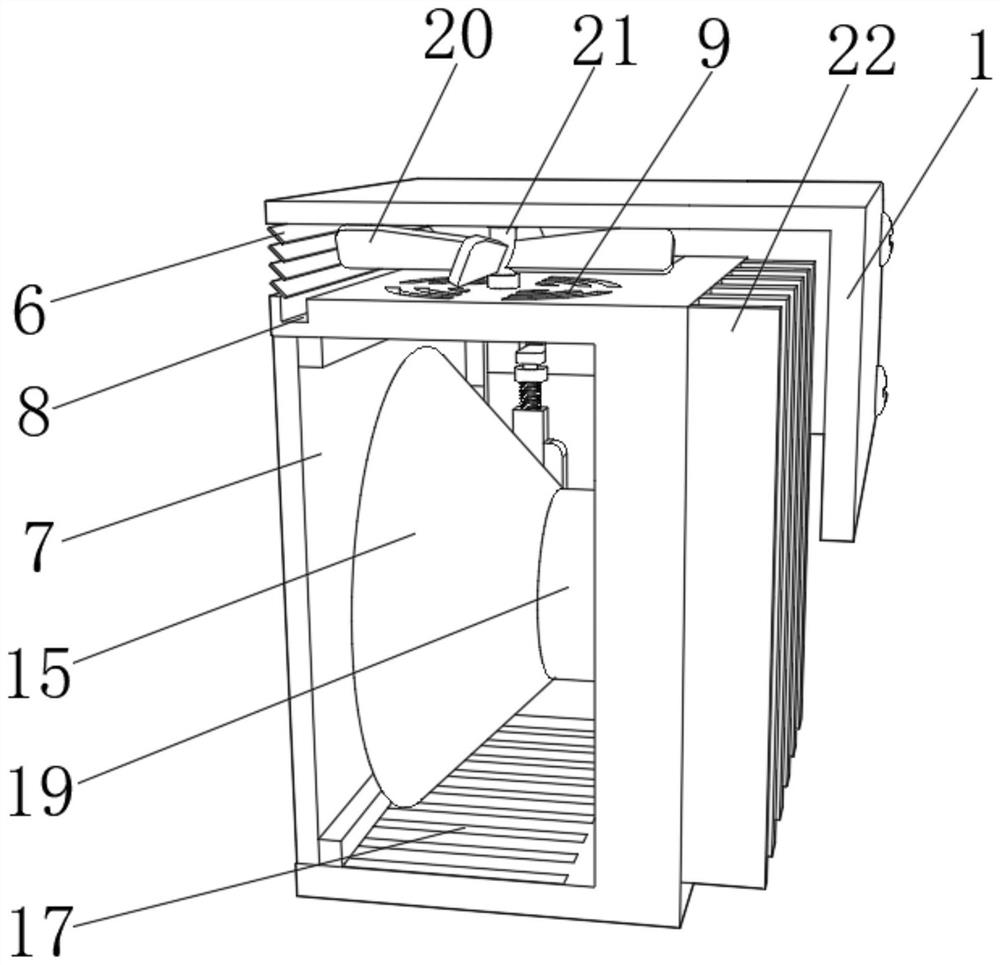
[0024] refer to Figure 1-Figure 3 , a car lamp with a heat dissipation function, comprising a lamp holder 5, a lamp holder 19 is fixed on one side of the lamp holder 5 by bolts, and a condenser cover 15 is fixed on one side of the lamp holder 19 by bolts, and the condenser cover 15 can be Improve the light intensity of the headlights to provide a better driving environment for the driver. One end of the lamp holder 19 is fixed with a lamp 16 by bolts, and the lamp 16 is located inside the spotlight 15, and the top of the lamp holder 5 is fixed with a windshield by bolts. 1. The inner wall of one side of the windshield 1 is fixed with a plurality of baffles 6 by bolts. The baffles 6 can block rainwater and prevent rainwater from entering the interior of the lamp. The upper surface of the lamp holder 5 is provided with a water collection tank 8. One side of 1 is provided with two drainage holes 2, and the drainage holes 2 are connected with the sump 8, and the rainwater collect...

Embodiment 2

[0028] refer to Figure 4, a car light with heat dissipation function, also includes a second fixed block 23, the bottom of the second fixed block 23 is fixed with a second spring 24 by bolts, and the second spring 24 can buffer the vibration caused by the running of the car, thereby The lamp 16 can be kept stable while the car is running. The other end of the second spring 24 is fixed with a splint 27 by bolts. The splint 27 can support the lamp holder 19. The inner wall of one side of the lamp holder 5 is provided with a mounting plate. Groove 25, one side of the mounting groove 25 is provided with two mounting holes, the connecting shaft 26 is rotatably connected in the mounting hole, and the connecting shaft 26 is rotatably connected with the lamp holder 19, under the rotation of the connecting shaft 26, the lamp holder 5 vibrates The generated offset angle can be offset, thereby avoiding the shaking of the lamp 16 when the vehicle is running, and improving the stability o...


PUM


Abstract

The invention discloses a car lamp with a heat dissipation function. The car lamp comprises a lamp bracket, and a lamp holder is fixedly connected to the inner wall of one side of the lamp bracket; one side of the lamp holder is fixedly connected with a light gathering cover; one end of the lamp holder is fixedly connected with a lamp; the lamp is positioned in the light gathering cover; the top end of the lamp bracket is fixedly connected with a wind shield; a plurality of baffles are fixedly connected to the inner wall of one side of the wind shield, a water collecting tank is formed in theupper surface of the lamp bracket, two drainage holes are formed in one side of the wind shield and communicated with the water collecting tank, and a rotating shaft is movably connected to the uppersurface of the lamp bracket and movably connected with the lower surface of the wind shield. According to the car lamp with the heat dissipation function, the cooling function can be better achieved,the use performance of a car lamp is improved, rainwater can be prevented from entering the lamp bracket to influence the car lamp, the safety of the car lamp is improved, the car lamp can be kept stable in the driving process of a car, and the stability of the car lamp is improved.

Description

technical field [0001] The invention relates to the technical field of auto parts, in particular to a car lamp with heat dissipation function. Background technique [0002] Car lights refer to the lamps and lanterns on the vehicle. It is a tool for vehicles to illuminate the road at night, and it is also a prompt tool for sending out various vehicle driving signals. As a light source, the lamp housing, lampshade, and reflector are all made of plastic materials, so they have the characteristics of low cost and light weight. However, during long-term driving at night, the car lights will generate a lot of heat and accumulate in the lampshade. , It is easy to cause the lights to burn out and cause certain losses to the user. [0003] After retrieval, the patent with authorized publication number CN210319840U discloses a heat dissipation vehicle lamp, which includes a mounting shell, a lamp body fixed in the mounting shell, and a heat dissipation structure connected to the end ...

Claims


Application Information

Patent Timeline
IPC IPC(8): F21S45/47F21S45/30F21S45/43F21V15/04F21V17/10F21W107/10
CPCF21V15/04F21V17/10F21S45/30F21S45/43F21S45/47F21W2107/10
Inventor 陆卫黄陆文辉
Owner 湖南德霸照明制造有限公司
Why Eureka
Try Eureka