Condenser rubber ball cleaning device

A technology for cleaning devices and condensers, which is applied to cleaning heat transfer devices, non-rotating equipment cleaning, lighting and heating equipment, etc. It can solve the problems of heat exchange efficiency decline, condenser end difference increase, rubber ball escape, etc. problems, to achieve the effect of ensuring safe and economical operation, increasing circulating water flow, and improving cleaning efficiency

Pending Publication Date: 2020-11-20
HUANENG POWER INTERNATIONAL
View PDF0 Cites 0 Cited by
  • Summary
  • Abstract
  • Description
  • Claims
  • Application Information

AI Technical Summary

Problems solved by technology

[0003] However, in the prior art, due to the arrangement of the circulation pump in the circulation pump room and the slight decrease in the output of one circulation pump after it has been changed to frequency conversion, the circulating water flow rate and flow rate of Unit 2 are lower than that of Unit 1. Due to the small flow rate during cleaning, the rubber balls cannot be recycled to the ball collector normally, and most of the rubber balls cannot even complete a cycle of cleaning. The temperature rise of circulating water decreases, reducing the economical operation of the unit; each side of the condenser rubber balls throws 1,000 balls each time, a large number of rubber balls escape, and the loss is huge

Method used


Image

  • Condenser rubber ball cleaning device

Examples


specific Embodiment

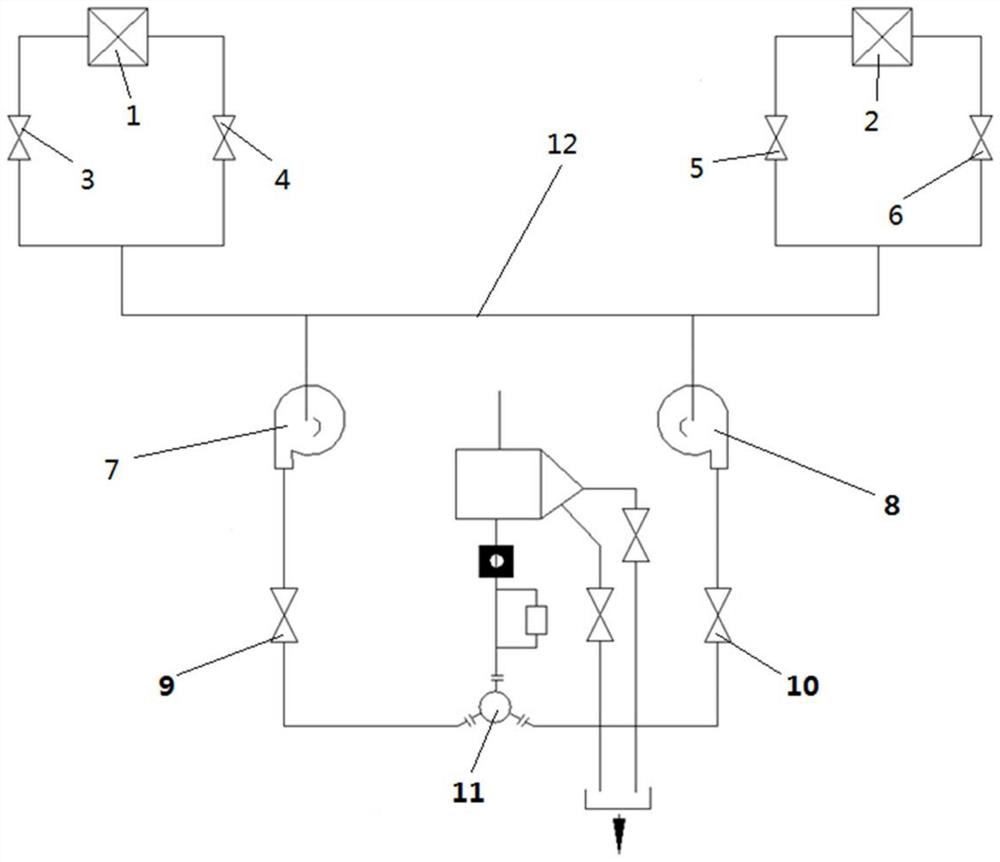
[0024] (1) Device structure and connection relationship:

[0025] Such as figure 1 The condenser rubber ball cleaning device shown is mainly composed of 2 ball collecting nets, 2 condenser ball cleaning pumps, 1 ball collector and 1 control cabinet. The ball collecting nets A and B are respectively placed in the condenser A and B circulating water outlet pipes. The ball collecting nets are opened when cleaning is not performed, and the ball collecting nets are closed when cleaning so that the rubber balls are in the condenser circulating water pipes. Clean cycle. The condenser small ball cleaning pump plays a role in promoting the circulation of small balls and collecting the balls. After the balls are recovered by the ball collecting net plate, the small balls are pumped out by the cleaning pump to the condenser circulating water inlet pipe. After cleaning the rubber balls of the condenser, close the ball collection net plate in the ball collector to collect the balls.

[...


PUM

PropertyMeasurementUnit
Diameteraaaaaaaaaa

Abstract

The invention relates to a condenser rubber ball cleaning device. The device comprises a condenser A side ball collecting net plate and a condenser B side ball collecting net plate, the condenser A side ball collecting net plate and the condenser B side ball collecting net plate are connected with a ball collector, two ends of each unit ball collecting net plate respectively and correspondingly pass through each inlet door of each condenser small ball cleaning pump, are respectively converged, and then are respectively and correspondingly connected with input ends of a first condenser small ball cleaning pump and a second condenser small ball cleaning pump, output ends of the first condenser small ball cleaning pump and the second condenser small ball cleaning pump are respectively and correspondingly connected with an outlet door of each condenser small ball cleaning pump, an outlet door of each condenser small ball cleaning pump is connected with a branching device, the branching device is also connected with a ball loading chamber and an electric control cabinet, and the input ends of the first condenser small ball cleaning pump and the second condenser small ball cleaning pumpare also independently connected through a communication pipeline. Compared with the prior art, the cleaning device has the advantages of remarkably increasing the flow of circulating water in the cleaning device, improving the ball collecting rate, ensuring the cleaning of the pipe wall and the like.

Description

technical field [0001] The invention relates to the technical field of condenser rubber ball cleaning, in particular to a condenser rubber ball cleaning device. Background technique [0002] Generally, power plants use units 1 and 2 to operate and generate electricity. Units 1 and 2 are 600MW supercritical pressure, one-time intermediate reheat, single-shaft, four-cylinder, four-exhaust, and reactionary condensing steam turbine units; each unit It is necessary to clean the condenser rubber ball once a month to ensure the cleanliness of the titanium tube of the condenser and the heat exchange efficiency of the cold end. [0003] However, in the prior art, due to the arrangement of the circulation pump in the circulation pump room and the slight decrease in the output of one circulation pump after it has been changed to frequency conversion, the circulating water flow rate and flow rate of Unit 2 are lower than that of Unit 1. Due to the small flow rate during cleaning, the r...

Claims


Application Information

Patent Timeline
IPC IPC(8): F28G1/12F28G15/00
CPCF28G1/12F28G15/00
Inventor 李晓辰陆哲珉吴剑孙臣璐朱丽霞
Owner HUANENG POWER INTERNATIONAL
Why Eureka
Try Eureka