Optical lens, camera device and terminal

A technology of optical lens and camera device, which is applied in the field of camera device and terminal, and optical lens, which can solve the problems of affecting the quality of picture shooting and increasing the risk of ghost image of optical lens, so as to reduce the risk of ghost image, ensure the quality of image shooting, and reduce the weight of the device. The effect of the design

Inactive Publication Date: 2020-11-20
JIANGXI JINGCHAO OPTICAL CO LTD
View PDF0 Cites 8 Cited by
  • Summary
  • Abstract
  • Description
  • Claims
  • Application Information

AI Technical Summary

Problems solved by technology

In related technologies, the effect of reducing the volume of the optical lens is often achieved by reducing the effective focal length of the optical lens, but this method is likely to increase the risk of ghost images of the optical lens and affect the quality of picture shooting

Method used


Image

  • Optical lens, camera device and terminal
  • Optical lens, camera device and terminal
  • Optical lens, camera device and terminal

Examples


no. 1 example

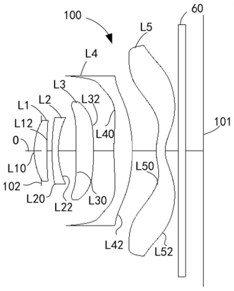
[0101] The structural diagram of the optical lens 100 disclosed in the first embodiment of the present application is as follows figure 1 As shown, the optical lens 100 includes a first lens L1, a second lens L2, a third lens L3, a fourth lens L4, a fifth lens L5 and an infrared filter 60 arranged in sequence along the optical axis O from the object side to the image side .

[0102] Wherein, the first lens L1 has a positive refractive power and includes a first object side L10 and a first image side L12, and the second lens L2 has a negative refractive power and includes a second object side L20 and a second image side L22. The third lens L3 has positive refractive power and includes a third object side L30 and a third image side L32. The fourth lens L4 has positive refractive power and includes a fourth object side L40 and a fourth image side L42. The fifth lens L5 has negative refractive power and includes a fifth object side L50 and a fifth image side L52.

[0103] Furth...

no. 2 example

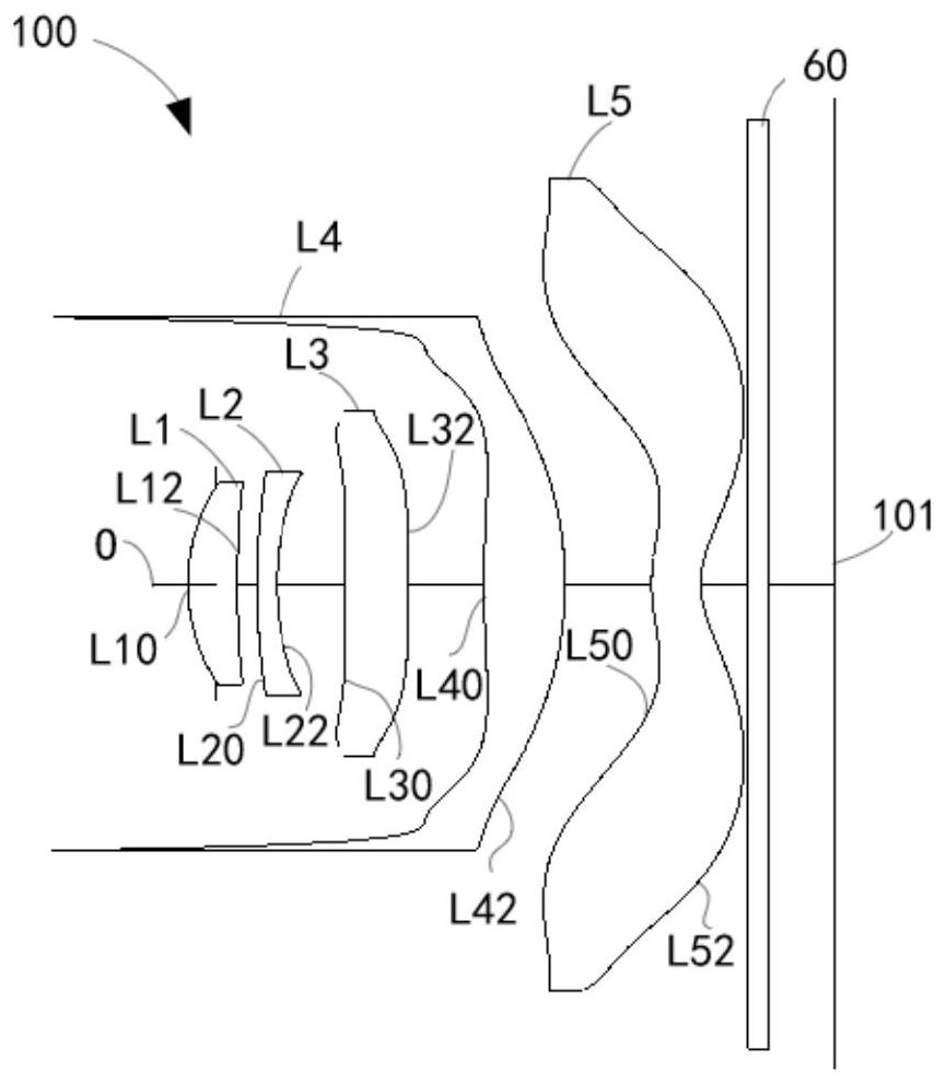
[0130] Please refer to image 3 , image 3 It is a schematic structural diagram of the optical lens 100 according to the second embodiment of the present application. The optical lens 100 includes a first lens L1 , a second lens L2 , a third lens L3 , a fourth lens L4 , a fifth lens L5 and an infrared filter 60 arranged sequentially from the object side to the image side.

[0131] Wherein, the first lens L1 has a positive refractive power and includes a first object side L10 and a first image side L12, and the second lens L2 has a negative refractive power and includes a second object side L20 and a second image side L22. The third lens L3 has positive refractive power and includes a third object side L30 and a third image side L32. The fourth lens L4 has positive refractive power and includes a fourth object side L40 and a fourth image side L42. The fifth lens L5 has negative refractive power and includes a fifth object side L50 and a fifth image side L52.

[0132] Furthe...

no. 3 example

[0146] Please refer to Figure 5 , Figure 5 A schematic structural diagram of the optical lens 100 according to the third embodiment of the present application is shown. The optical lens 100 includes a first lens L1 , a second lens L2 , a third lens L3 , a fourth lens L4 , a fifth lens L5 and an infrared filter 60 arranged sequentially from the object side to the image side.

[0147] Wherein, the first lens L1 has a positive refractive power and includes a first object side L10 and a first image side L12, and the second lens L2 has a negative refractive power and includes a second object side L20 and a second image side L22. The third lens L3 has negative refractive power and includes a third object side L30 and a third image side L32. The fourth lens L4 has positive refractive power and includes a fourth object side L40 and a fourth image side L42. The fifth lens L5 has negative refractive power and includes a fifth object side L50 and a fifth image side L52.

[0148] Fu...


PUM


Abstract

The invention discloses an optical lens, a camera device and a terminal. The optical lens comprises a first lens, a second lens, a third lens, a fourth lens and a fifth lens which are sequentially arranged from the object side to the image side along the optical axis. The first lens has positive focal power, and the object side surface of the first lens is a convex surface near the optical axis; the second lens has focal power; the third lens has focal power; the fourth lens has positive focal power, and the image side surface of the fourth lens is a convex surface near the optical axis; the fifth lens has negative focal power, and the image side surface of the fifth lens is a concave surface near the optical axis; and the optical lens satisfies the following relationship: 2<SD1 / CT12<12. According to the optical lens, through the focal power of the five-piece lens and the convex-concave design of the object side surface and the image side surface, and the met relationship: 2<SD1 / CT12<12, the size of the head of the optical lens can be effectively reduced, so that the width of the optical lens in the direction perpendicular to the optical axis is reduced, the overall size of the optical lens is compressed, the compactness of the optical lens is improved, the ghost image risk can be reduced, and the image shooting quality is ensured.

Description

technical field [0001] The present invention relates to the technical field of optical imaging, in particular to an optical lens, an imaging device and a terminal. Background technique [0002] Optical lenses for optical imaging are widely used in terminals such as smartphones, tablet computers, and cameras. Taking smart phones as an example, in order to meet the different shooting needs of users, a smart phone is usually equipped with multiple optical lenses with different characteristics and application environments. The miniaturization design also puts forward the requirement. In related technologies, the effective focal length of the optical lens is often reduced to achieve the effect of reducing the volume of the optical lens, but this method tends to increase the risk of ghost images of the optical lens and affect the quality of picture shooting. Contents of the invention [0003] The embodiment of the present invention discloses an optical lens, an imaging device ...

Claims


Application Information

Patent Timeline
Patent Type & Authority Applications(China)
IPC IPC(8): G02B13/00G02B13/18
CPCG02B13/0045G02B13/008G02B13/18
Inventor 曾晗谭怡翔杨懿刘秀李明
Owner JIANGXI JINGCHAO OPTICAL CO LTD
Why Eureka
Try Eureka