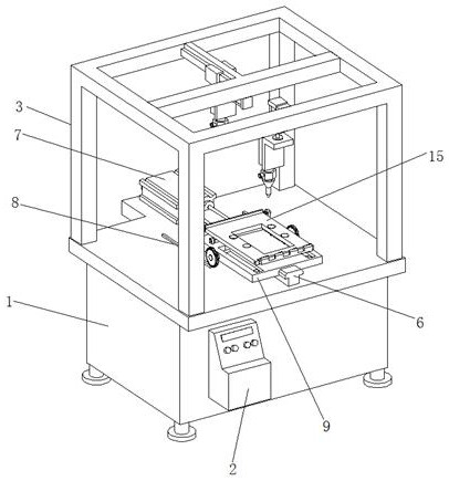
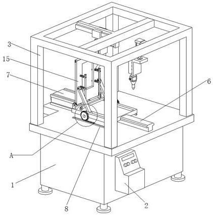
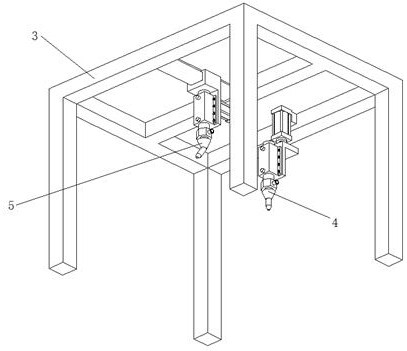
Full-automatic screen turnover machine for liquid crystal module

A liquid crystal module, fully automatic technology, applied in the direction of nonlinear optics, instruments, optics, etc., can solve the problems of multiple power sources, winding of rotating mechanisms, vacuum generators that generate vacuum, etc., and achieve simple structure, strong linkage, Solve the effect of high failure rate

Inactive Publication Date: 2020-11-20
界首泰谷工业设计有限公司
View PDF1 Cites 3 Cited by
  • Summary
  • Abstract
  • Description
  • Claims
  • Application Information

AI Technical Summary

Problems solved by technology

The stage turning mechanism disclosed in this invention drives the entire stage to rotate 180° through the turning drive (ie, the servo motor), and at the same time realizes the fixing of the liquid crystal display screen through the suction cup in the adsorption unit. Flip and fix in the production process, but the whole mechanism has many power sources, including the push device that pushes the entire support frame to move along the mobile module, the servo motor that drives the stage to turn over, and the vacuum generator that makes the vacuum inside the suction cup, etc., when When one of the power sources fails, the entire turning mechanism cannot operate normally; in addition, because the suction cup and the vacuum generator need to be connected through the air pipe, the entire turning mechanism is constantly rotating back and forth during the working process, which is used to connect the suction cup and the vacuum The air tube of the generator is easily entangled with the rotating mechanism, resulting in damage to the air tube

Method used


Image

  • Full-automatic screen turnover machine for liquid crystal module
  • Full-automatic screen turnover machine for liquid crystal module
  • Full-automatic screen turnover machine for liquid crystal module

Examples


Embodiment Construction

[0028] In order to enable those skilled in the art to better understand the solution of the present application, the technical solution in the embodiment of the application will be clearly and completely described below in conjunction with the accompanying drawings in the embodiment of the application. Obviously, the described embodiment is only It is an embodiment of a part of the application, but not all of the embodiments. Based on the embodiments in this application, all other embodiments obtained by persons of ordinary skill in the art without creative efforts shall fall within the scope of protection of this application.

[0029] It should be noted that the terms "first" and "second" in the description and claims of the present application and the above drawings are used to distinguish similar objects, but not necessarily used to describe a specific sequence or sequence. It should be understood that the data so used may be interchanged under appropriate circumstances for...


PUM


Abstract

The invention relates to the technical field of liquid crystal module production, and particularly discloses a full-automatic screen turnover machine for a liquid crystal module. The full-automatic screen turnover machine comprises a case and a control cabinet; the control cabinet is arranged on the front side surface of the case; a slide rail is arranged on the upper surface of the case; a pushing device is arranged on the upper surface of the case on the rear side of the sliding rail; toothed bars are arranged on the upper surface of the case at the left side and the right side of the sliding rail; a pushing plate is arranged on the sliding rail; a sliding groove matched with the sliding rail is formed in the lower surface of the pushing plate; the front end of the pushing device is connected with the pushing plate; storage grooves parallel to the sliding groove are formed in the upper surface of the pushing plate; and rotating rods are rotationally arranged at the rear ends of the storage grooves. According to the invention, three steps of position movement of the liquid crystal module carrier plate, turnover of the liquid crystal module carrier plate and adsorption and fixationof a sucker to the liquid crystal module can be realized only through the pushing and traction processes of one pushing device, and the problem that the failure rate is high due to the fact that an existing carrying table turnover mechanism for liquid crystal module dispensing needs to be used in cooperation with multiple power sources is effectively solved.

Description

technical field [0001] The invention relates to the technical field of liquid crystal module production, and specifically discloses a fully automatic screen turning machine for liquid crystal modules. Background technique [0002] The liquid crystal module is an important component of the liquid crystal display. The liquid crystal module is simply composed of the liquid crystal display and the backlight assembly. In the production process of LCD modules, glue dispensing is an important process, and double-sided glue dispensing is required for LCD screens. Specifically, a glue dispensing mechanism is used to dispense glue on the front of the liquid crystal display, and then the liquid crystal display is turned 90 to 180° by a turning mechanism, and then glue is dispensed on the back of the liquid crystal display. [0003] For example, the patent No. CN110369232A discloses a stage turning mechanism, glue dispensing device and display production line. The stage turnover mecha...

Claims


Application Information

Patent Timeline
Patent Type & Authority Applications(China)
IPC IPC(8): G02F1/13
CPCG02F1/1303
Inventor 余秀芳
Owner 界首泰谷工业设计有限公司
Why Eureka
Try Eureka