
Power tunnel cable rack

A technology for power tunnels and cable racks, which is applied to cable installation in tunnels, cable installation in underground pipes, cable installation, etc. Simple construction and the effect of increasing static friction

Inactive Publication Date: 2020-11-20
鼎固建安集团有限公司
View PDF6 Cites 7 Cited by
  • Summary
  • Abstract
  • Description
  • Claims
  • Application Information

AI Technical Summary

Problems solved by technology

[0005] In view of the above-mentioned related technologies, the inventor believes that there are the following defects: due to the different uses of the cables and the different voltages of the cables, when the cables are laid, the vertical distance between layers between two adjacent horizontal supports is different. The vertical support is generally installed on the structure through expansion bolts or positioning pins. When the purpose of the laid cable is changed and the distance between two adjacent horizontal supports needs to be adjusted, the vertical support and the horizontal support must be removed. At the same time, it will cause certain damage to the structure, and it is inconvenient to adjust

Method used


Image

  • Power tunnel cable rack
  • Power tunnel cable rack
  • Power tunnel cable rack

Examples


Embodiment 1

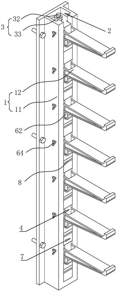
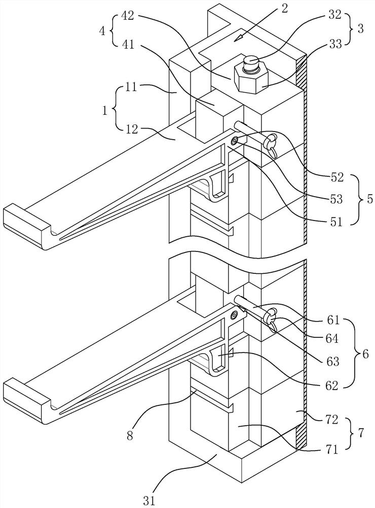
[0038] The embodiment of the present application discloses a power tunnel cable rack. refer to figure 1 , figure 2 , The power tunnel cable rack includes a support body 1, and the support body 1 is evenly provided with installation holes along both sides of the vertical direction, and expansion bolts are installed in the installation holes, and the support body 1 is fixed and installed in the cable tunnel or cable trench by expansion bolts The bracket body 1 includes a column 11 and a plurality of bracket arms 12, and a plurality of bracket arms 12 are evenly installed on the column 11 along the vertical direction, and a plurality of bracket arms 12 are arranged in a horizontal state, and there are vertically arranged in the column 11 Install the through slot 2, the installation through slot 2 is stacked with a plurality of adjusting parts 7 and a plurality of connecting parts 4 along the vertical direction, at least two adjusting parts 7 are mounted between two adjacent con...

Embodiment 2

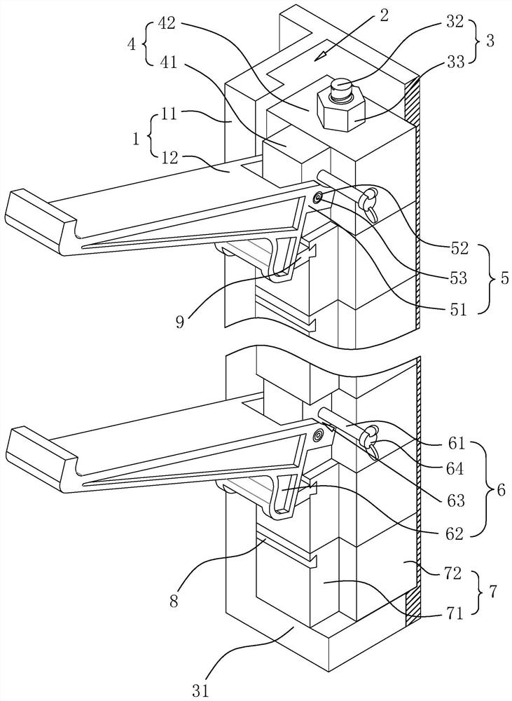
[0045] refer to image 3 The difference between this embodiment and Embodiment 1 is that the side of the adjustment block 71 close to the bracket arm 12 is provided with an insertion slot 8 along the horizontal direction, and the insertion slot 8 is inserted with a bracket for adjusting the bracket arm 12 and the column 11. The adjustment block three 9 of the included angle, when the column 11 is obliquely installed in the cable tunnel or cable trench, in order to increase the contact area between the adjustment block three 9 and the limit block 62, the adjustment block three 9 is a right-angled trapezoid, and the adjustment Block 3 9 is welded with an insertion block matching the insertion groove 8 on one side near the column 11, the adjustment block 3 9 is inserted in the insertion groove 8 through the insertion block, and the inclined surface of the adjustment block 3 9 is away from the column 11- The side is inclined downward, and the slope of the adjustment block 9 fits w...


PUM


Abstract

The invention relates to the technical field of tunnel cable installation, in particular to a power tunnel cable rack. The rack comprises a rack body, the rack body comprises a stand column and a plurality of supporting arms. The multiple supporting arms are evenly arranged on the stand column in the vertical direction. The plurality of supporting arms are horizontally arranged; the rack body further comprises a plurality of adjusting pieces and a plurality of connecting pieces, the adjusting pieces and the connecting pieces are arranged in the stand column in a stacked mode in the vertical direction, at least two adjusting pieces are arranged between every two adjacent connecting pieces, and the supporting arms are rotationally arranged on the connecting pieces and attached to the adjusting pieces close to one side of the stand column. The power tunnel cable rack has the effects of being convenient to operate and simple in construction.

Description

technical field [0001] The present application relates to the field of tunnel cable installation technology, in particular to a power tunnel cable rack. Background technique [0002] At present, cable tunnels and cable trenches are the main channels for urban power supply. Cable supports are fixed on the inner walls of cable tunnels and cable trenches, and cables are laid in cable trenches and tunnels through cable supports. Commonly used cable brackets are assembled brackets, and assembled brackets are also called combined cable brackets. The components of the brackets are produced in the factory according to the requirements that the brackets can be directly installed on site. After the cable structure is completed, before the cable is laid or the cable is laid Cable brackets installed directly on site during the process. [0003] The patent document of the existing notification number CN104485623B discloses a telescopic tunnel cable support, including a support composed ...

Claims


Application Information

Patent Timeline
IPC IPC(8): H02G9/08H02G9/02H02G9/06H02G3/02
CPCH02G3/02H02G9/02H02G9/06H02G9/08
Inventor 田国梁胡小风
Owner 鼎固建安集团有限公司
Learn More