
Driving circuit of transistor and pressure wave balloon angioplasty treatment system

A technology for driving circuits and transistors, applied in electrical components, output power conversion devices, medical science and other directions, can solve the problems of poor stability of Marx generators, inability to ensure the conduction of transistors at all levels, low reliability, etc., to avoid current The effect of pouring back, improving stability and safety, improving stability and reliability

Pending Publication Date: 2020-11-20
SONOSEMI MEDICAL CO LTD
View PDF0 Cites 1 Cited by
  • Summary
  • Abstract
  • Description
  • Claims
  • Application Information

AI Technical Summary

Problems solved by technology

[0004] The purpose of this application is to provide a driving circuit for transistors, aiming to solve the problem that in the process of discharging capacitors in series in the traditional Marx generator technical scheme, since the gate-source voltage of each transistor is floating, it cannot be guaranteed Transistors at all levels remain on during the discharge of capacitors in series, resulting in poor stability and low reliability of the Marx generator

Method used


Image

  • Driving circuit of transistor and pressure wave balloon angioplasty treatment system
  • Driving circuit of transistor and pressure wave balloon angioplasty treatment system
  • Driving circuit of transistor and pressure wave balloon angioplasty treatment system

Examples


Embodiment Construction

[0049] In order to make the technical problems, technical solutions and beneficial effects to be solved by the present application clearer, the present application will be further described in detail below in conjunction with the accompanying drawings and embodiments. It should be understood that the specific embodiments described here are only used to explain the present application, and are not intended to limit the present application.

[0050] It should be noted that when an element is referred to as being “fixed” or “disposed on” another element, it may be directly on the other element or be indirectly on the other element. When an element is referred to as being "connected to" another element, it can be directly connected to the other element or indirectly connected to the other element.

[0051]It should be understood that the terms "first" and "second" are used for descriptive purposes only, and cannot be interpreted as indicating or implying relative importance or imp...


PUM


Abstract

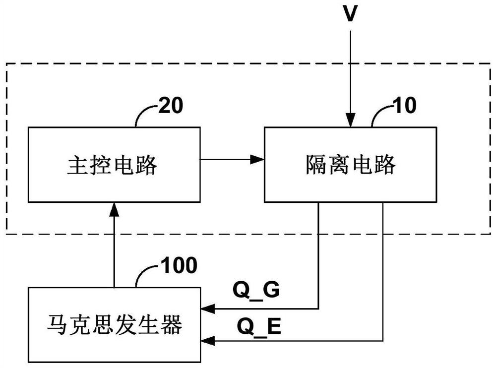
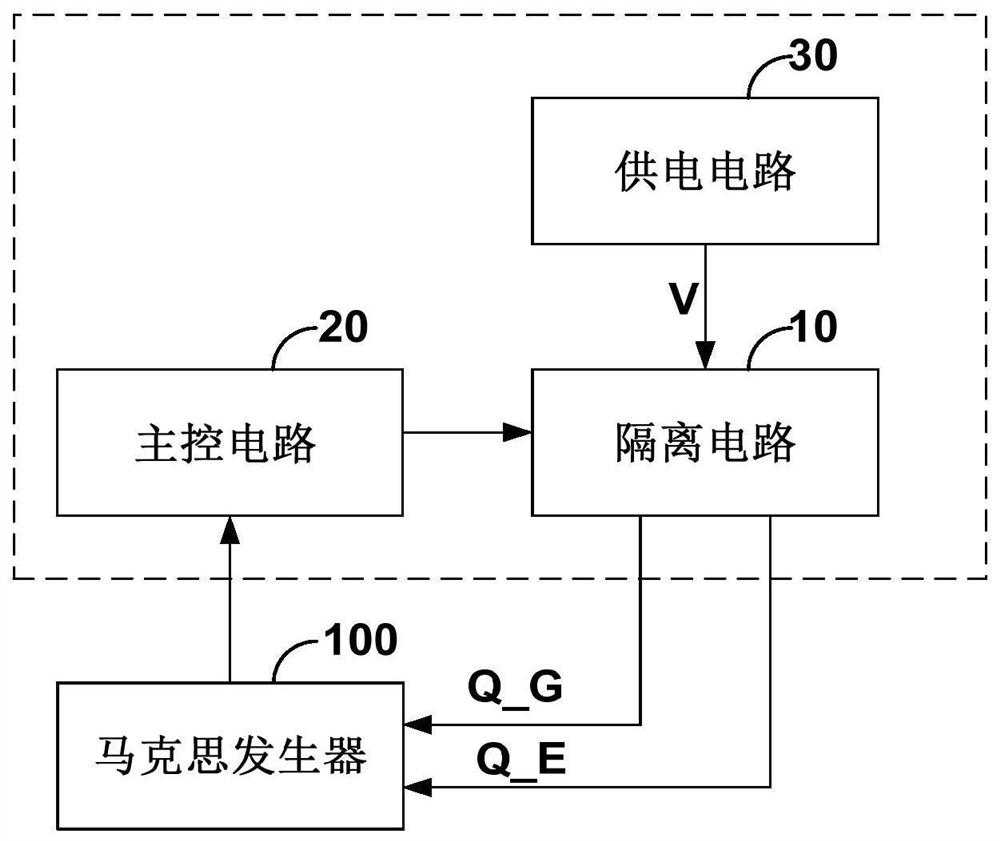
The invention discloses a driving circuit of a transistor and a pressure wave balloon angioplasty treatment system. The transistor controls a corresponding capacitor in the marx generator to perform parallel charging and series discharging, and the marx generator is applied to a high-voltage pulse power supply host in the pressure wave balloon angioplasty treatment system and used for treating andeliminating calcified plaques in a vascular wall so as to recover normal blood flow in a blood vessel; and the driving circuit comprises an isolation circuit and a main control circuit. When the maincontrol circuit receives an instruction of series discharge of the corresponding capacitor in the marx generator, the main control circuit sends out an instruction to control the isolation circuit tobe switched on. The isolation circuit receives a target electric signal when being conducted, and outputs a driving signal to a position between the gate and the source of the transistor, so that thetransistor is kept conducted. According to the driving circuit, when the capacitors of all levels in the marx generator are connected in series for discharging, the driving signal is output under thecondition that the gate-source voltage of each transistor floats, conduction of the transistors is maintained, and the stability and reliability during discharging of the marx generator are improved.

Description

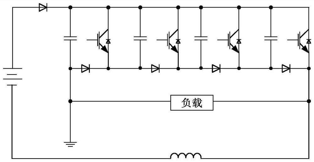
technical field [0001] The application belongs to the technical field of medical high-voltage pulse power supply, and in particular relates to a transistor drive circuit and a pressure wave balloon angioplasty treatment system. Background technique [0002] Such as figure 1 As shown, the Marx Generator (Marx Generator) is a device that generates high-voltage pulses through a low-voltage DC power supply by charging n-level capacitors in parallel and then discharging them in series. The Marx generator has transistors, and all transistors are turned off during the capacitor charging phase. When the low-voltage DC power supply is turned off, the output current of the low-voltage DC power supply flows to the capacitors at all levels, so that the voltages of the capacitors at all levels reach the voltage V1 of the low-voltage DC power supply; in the capacitor series discharge stage, all transistors are turned on, and the capacitors at all levels are connected in series through the...

Claims


Application Information

Patent Timeline
IPC IPC(8): H02M9/04H02M1/08A61B17/22
CPCA61B17/22004A61B17/22022A61B2017/22001H02M1/08H02M11/00
Inventor 温运生刘斌
Owner SONOSEMI MEDICAL CO LTD
Learn More