Supercharge Your Innovation With Domain-Expert AI Agents!

Encoding and decoding circuit for multi-channel digital signal transmission

A digital signal and decoding circuit technology, applied in the field of codec circuits, can solve the problems of transmission jitter, sampling error, and the delay between output signals and input signals are not fixed, and achieve the effect of small chip area and power consumption reduction.

Active Publication Date: 2020-11-20
SUZHOU NOVOSENSE MICROELECTRONICS
View PDF7 Cites 2 Cited by
  • Summary
  • Abstract
  • Description
  • Claims
  • Application Information

AI Technical Summary

Problems solved by technology

However, in this method, the sampling circuit will have a sampling error, which will cause transmission jitter
The multi-channel input signal is sent to the encoding circuit under the action of the sampling signal, and the asynchrony between the sampling signal and the multi-channel input signal will cause the time delay between the output signal and the input signal to be unstable.

Method used


Image

  • Encoding and decoding circuit for multi-channel digital signal transmission
  • Encoding and decoding circuit for multi-channel digital signal transmission

Examples


Embodiment Construction

[0020] In order to enable those skilled in the art to better understand the technical solutions in the present invention, the technical solutions in the embodiments of the present invention will be clearly and completely described below in conjunction with the drawings in the embodiments of the present invention. Obviously, the described The embodiments are only some of the embodiments of the present invention, not all of them. Based on the embodiments of the present invention, all other embodiments obtained by persons of ordinary skill in the art without making creative efforts shall fall within the protection scope of the present invention.

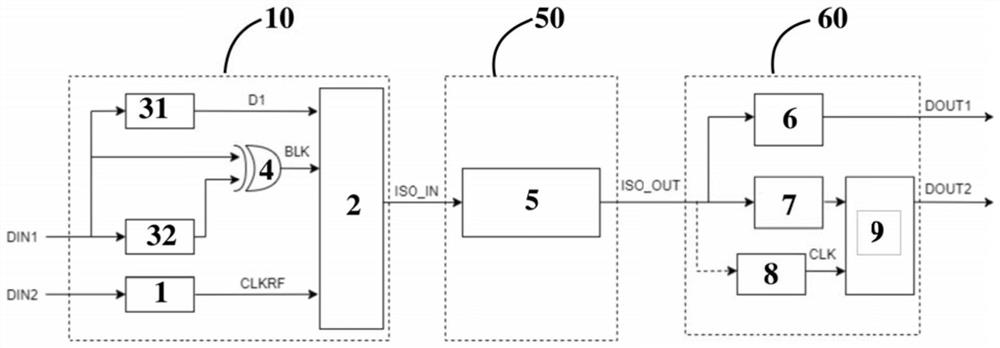
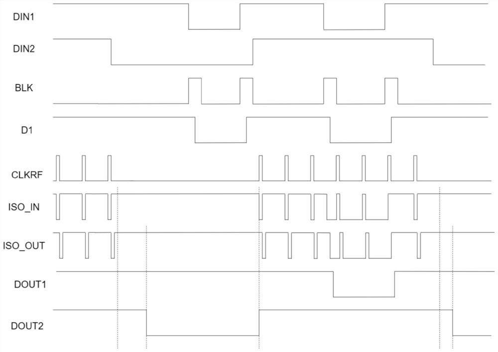
[0021] Such as Figure 1 to Figure 2 As shown, the present invention provides a codec circuit for multi-channel digital signal transmission, including an encoding circuit 10, a transmission channel 50, and a decoding circuit 60 connected in sequence, and the encoding circuit 10 includes an edge modulation circuit, a refresh circuit 1 an...


PUM


Abstract

The invention provides an encoding and decoding circuit for multi-channel digital signal transmission. The circuit comprises an encoding circuit, a transmission channel and a decoding circuit which are connected in sequence. The encoding circuit comprises an edge modulation circuit, a refreshing circuit and a modulator, wherein a first input signal is input into the edge modulation circuit, a second input signal is input into the refreshing circuit, the output end of the edge modulation circuit and the output end of the refreshing circuit are connected with the modulator, and the modulator outputs a modulation signal and sends the modulation signal to the transmission channel. The decoding circuit correspondingly decodes a first output signal and a second output signal.

Description

technical field [0001] The invention relates to a codec circuit, in particular to a codec circuit for multi-channel digital signal transmission. Background technique [0002] In the application of digital isolators, it is often necessary to transmit more than one input signal at the same time, and the isolator can realize the electrical isolation of the input terminal and the output terminal. In the first prior art, a single-channel digital isolator is used for each input signal. However, in this case, the number of digital isolators must be the same as the number of input signals, which occupies a large area and is relatively costly. higher. [0003] In the second prior art, the sampling signal can be used to sample multiple (two or more) input signals, and the sampling results are sent to the encoding circuit for encoding, and then transmitted through the isolator. Finally, it is decoded by a decoding circuit and output. At this time, the number of channels of the isola...

Claims


Application Information

Patent Timeline
IPC IPC(8): H03K19/00
CPCH03K19/0016
Inventor 盛云孙园杰张昊
Owner SUZHOU NOVOSENSE MICROELECTRONICS
Features
  • R&D
  • Intellectual Property
  • Life Sciences
  • Materials
  • Tech Scout
  • Unparalleled Data Quality
  • Higher Quality Content
  • 60% Fewer Hallucinations
Learn More