
Village-in-city deep coverage type optical fiber distribution scheme

A technology of deep coverage and fiber distribution, applied in fiber transmission, fiber radio, network planning, etc., can solve problems affecting call quality, waste of base station resources, etc., to reduce call drop rate, reduce wiring costs, and improve system access success. rate effect

Inactive Publication Date: 2020-11-20
JIANGSU YONGDING COMM
View PDF6 Cites 0 Cited by
  • Summary
  • Abstract
  • Description
  • Claims
  • Application Information

AI Technical Summary

Problems solved by technology

The actual use results in some places show that the signals of multiple base stations form many overlapping areas in densely populated areas. When users talk in these areas, it is easy to cause base station switching and affect the call quality. In addition, this solution also causes base station Big waste of resources

Method used


Image

  • Village-in-city deep coverage type optical fiber distribution scheme
  • Village-in-city deep coverage type optical fiber distribution scheme

Examples


Embodiment Construction

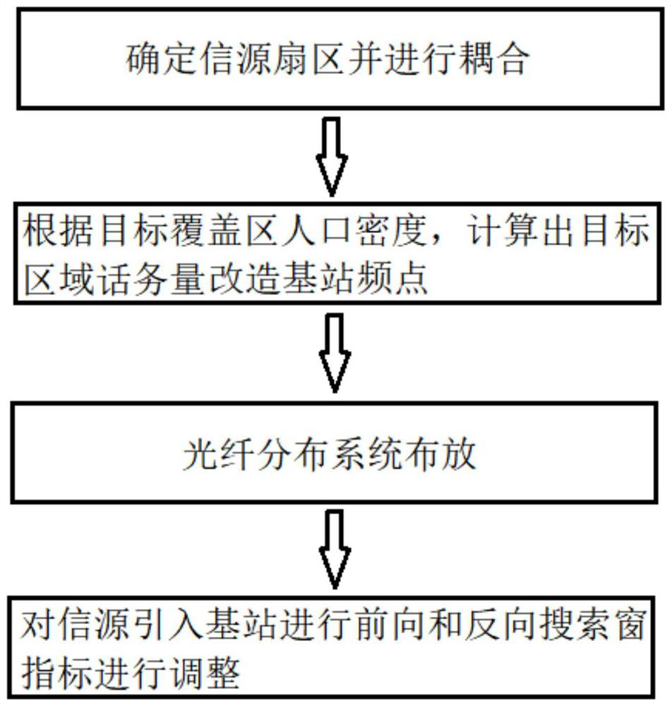
[0018] The technical solution provided by the present invention will be further explained below. The present invention provides the following technical solution: a deep coverage optical fiber distribution scheme for urban villages, which is characterized in that it includes the following steps:

[0019] S1: Determine the source sector, grasp the PN code distribution of the base station in the target coverage area, determine the sector signal of the base station in the target coverage area, and couple the sector signal in the target coverage area;

[0020] S2: traffic capacity accounting, according to the population density of the target coverage area, calculate the traffic volume of the target area, and then transform the base station frequency point according to the traffic volume;

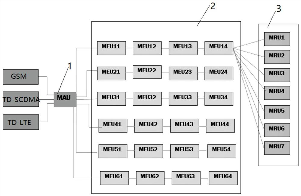
[0021] S3: Deployment of the optical fiber distribution system. The main unit 1 of the optical fiber distribution system is centrally placed in the centralized source computer room, and the optica...


PUM


Abstract

A village-in-city deep coverage type optical fiber distribution scheme comprises the following steps of: mastering PN code distribution of a base station in a target coverage region, determining sector signals of the base station in the target coverage region, and coupling the sector signals of the target coverage region; calculating telephone traffic of a target region according to the populationdensity of the target coverage region, and reconstructing base station frequency points according to the telephone traffic; arranging optical fiber distribution system main units in a centralized information source machine room in a centralized mode, routing optical fibers along streets, adopting outdoor far-end units in most regions of villages in cities, and integrally installing the outdoor far-end units and antennas along the streets; and adjusting forward and reverse search window indexes of an information source introduction base station. The village-in-city deep coverage type optical fiber distribution scheme provides an optical fiber distribution system, which comprises an information source, main units, expansion units and far-end units, wherein the main units are connected withthe multiple expansion units, the expansion units are connected with the multiple far-end units, and the main units are connected with the expansion units through the optical cables.

Description

technical field [0001] The invention relates to an optical fiber distribution scheme, in particular to an urban village deep coverage optical fiber distribution scheme. Background technique [0002] With the rapid development of communication technology and the national economy, people have higher and higher requirements on the quality of wireless communication coverage. The goal of operators is to provide people with high-quality mobile communication services anytime and anywhere. For this reason, communication operators, on the one hand, increase the strength of base station network optimization, and on the other hand, increase signal coverage for specific environments that are prone to coverage blind spots. [0003] Take an urban village as an example. It is a relatively independent residential area, mostly private houses. It is inconvenient to install base stations in it, and the distance between houses is very small. The signal attenuation is particularly severe, and i...

Claims


Application Information

Patent Timeline
Patent Type & Authority Applications(China)
IPC IPC(8): H04B10/25H04B10/2575H04B10/272H04W16/18H04W16/20
CPCH04B10/25754H04B10/272H04W16/18H04W16/20
Inventor 李大庆
Owner JIANGSU YONGDING COMM
Learn More