Stator with a cooling jacket, electric machine and motor vehicle

A technology for cooling jackets and motor vehicles, which is applied in the direction of electric components, cooling/ventilation devices, electromechanical devices, etc., and can solve problems such as motor failure and motor overheating

Active Publication Date: 2020-11-20
BAYERISCHE MOTOREN WERKE AG
View PDF9 Cites 0 Cited by
  • Summary
  • Abstract
  • Description
  • Claims
  • Application Information

AI Technical Summary

Problems solved by technology

Motor overheating can even lead to motor failure

Method used


Image

  • Stator with a cooling jacket, electric machine and motor vehicle
  • Stator with a cooling jacket, electric machine and motor vehicle
  • Stator with a cooling jacket, electric machine and motor vehicle

Examples


Embodiment Construction

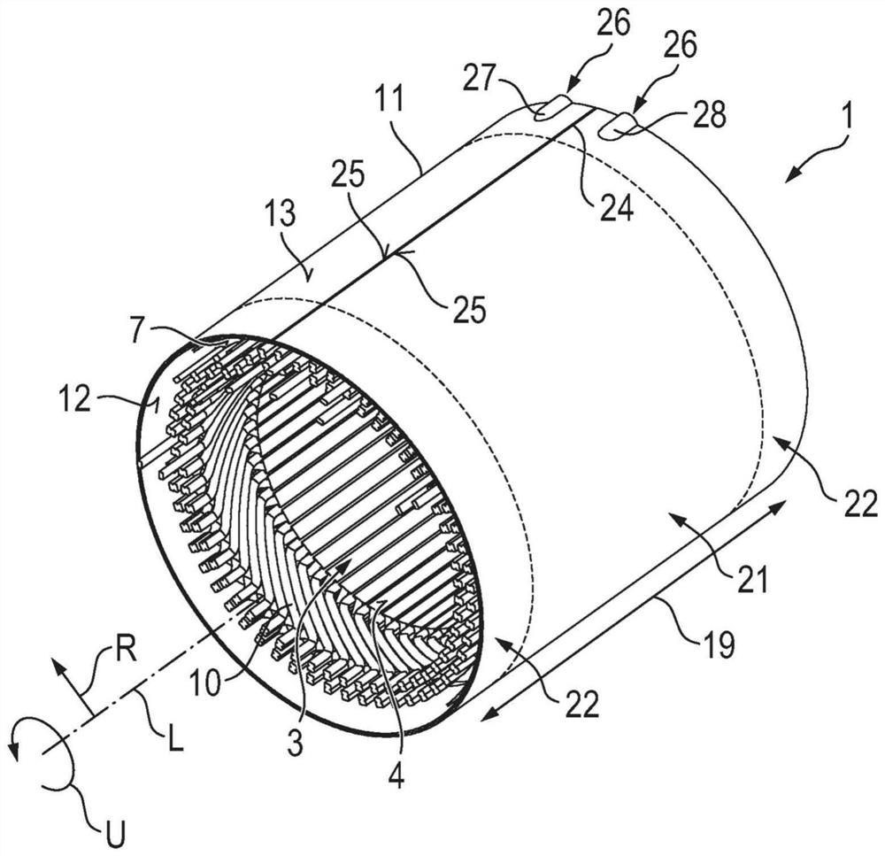
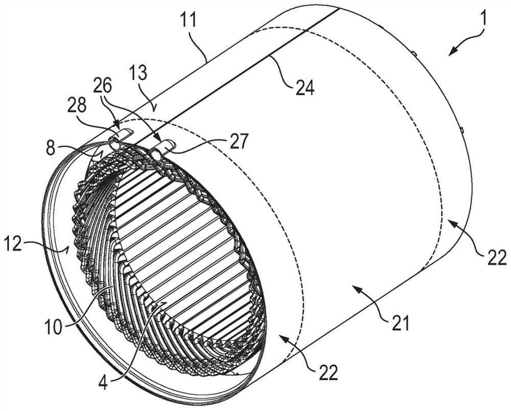
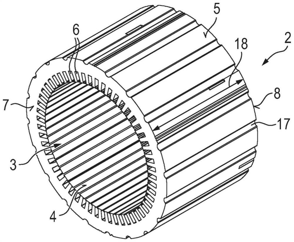
[0041] figure 1 and figure 2 A first embodiment of a stator 1 for an electric machine of an electrically driveable motor vehicle, not shown here, is shown from a different perspective. The stator 1 has a lamination stack 2 which is in image 3 shown as a separate illustration. The laminated core 2 is formed circumferentially around the longitudinal axis L of the stator 1 in the circumferential direction U and is hollow-cylindrical. The longitudinal axis L also corresponds to the axis of rotation about which the rotor, not shown here, which is mounted in the cylindrical cavity 3 of the laminated core 2 , rotates. The laminated core 2 has an inner side 4 surrounding the cylindrical cavity 3 . Furthermore, the laminated core 2 has an outer side 5 opposite the inner side 4 in the radial direction R. A plurality of winding slots 6 are formed distributed in the circumferential direction U in the inner side 4 of the laminated core 2 . The winding slots 6 extend axially along t...


PUM


Abstract

The invention relates to a stator (1) for an electric machine of a motor vehicle, comprising a laminated core (2) having an inner side (4) with winding grooves (6) and having an outer side (5), windings (9), which are arranged in the winding grooves (6) and form winding heads (10) on axially opposing front faces (7, 8) of the laminated core (2), and a cooling jacket (11) which conducts cooling fluid and has a first metal sheet (12) which forms an inner wall of the cooling jacket (11) facing the laminated core (2), and a second metal sheet (13) which forms an outer wall of the cooling jacket (11) surrounding the inner wall, wherein an axial height (19) of the cooling jacket (11) exceeds an axial height (18) of the laminated core (2), and the cooling jacket (11) has a laminated-core coolingjacket region (21) for encasing the laminated core (2) and two axially opposing winding-head cooling jacket regions (22) adjoining the laminated-core cooling jacket region (21) for encasing the winding heads (10). The invention also relates to an electric machine and to a motor vehicle.

Description

technical field [0001] The invention relates to a stator for an electric machine of a motor vehicle, which has a laminated core with an inner side facing the cavity and an outer side which has a plurality of axial extensions in the circumferential direction winding slots. Furthermore, the stator has windings which are arranged in winding slots and form winding heads on axially opposite end sides of the laminated core. In addition, the stator has a cooling jacket which conducts a cooling fluid, the cooling jacket having a first metal plate which forms the inner wall of the cooling jacket facing the lamination stack and a second metal plate which forms the cooling The outer wall of the sleeve surrounding the inner wall, one of the metal sheets is designed without structure and the other metal sheet is configured with a structure of recesses and protrusions, the metal sheets are joined together in the region of the recesses Furthermore, at least one cooling channel for conducti...

Claims


Application Information

Patent Timeline
Patent Type & Authority Applications(China)
IPC IPC(8): H02K5/20H02K9/19
CPCH02K5/203H02K1/20H02K9/193
Inventor J·梅茨J·拉戈特T·霍夫勒F·博洛尼科夫
Owner BAYERISCHE MOTOREN WERKE AG
Why Eureka
Try Eureka