Turbine

a turbine and turbine technology, applied in the field of turbines, can solve the problems of not much higher manufacturing cost of induction turbines, and achieve the effects of reducing pressure losses, increasing efficiency of rankine cycles, and compact structur

Active Publication Date: 2015-02-12
EQUITHERM S A R L
View PDF1 Cites 0 Cited by
  • Summary
  • Abstract
  • Description
  • Claims
  • Application Information

AI Technical Summary

Benefits of technology

[0021]A preferred embodiment of the turbine may further comprise a first vapour drum that is located in axial extension of the axial main vapour inlet port and directly connected to the latter without any intermediate piping, and a second vapour drum that is located in axial extension of the annular secondary vapour inlet port and directly connected to the latter without any intermediate piping, wherein the second vapour drum is preferably a compartment inside the first vapour drum, or the first vapour drum is, more preferably, a compartment inside the second vapour drum. The axial vapour inlet port advantageously comprises a first tubular vapour inlet connection, which is engaged in a sliding and sealed manner by the first vapour

Problems solved by technology

The manufacturing costs for the induction type turbine are n

Method used


Image

  • Turbine
  • Turbine
  • Turbine

Examples


Embodiment Construction

[0031]It will be understood that the following description and the drawings to which it refers describe by way of example preferred embodiments of the claimed subject matter for illustration purposes. The description and drawings shall not further limit the scope, nature or spirit of the claimed subject matter.

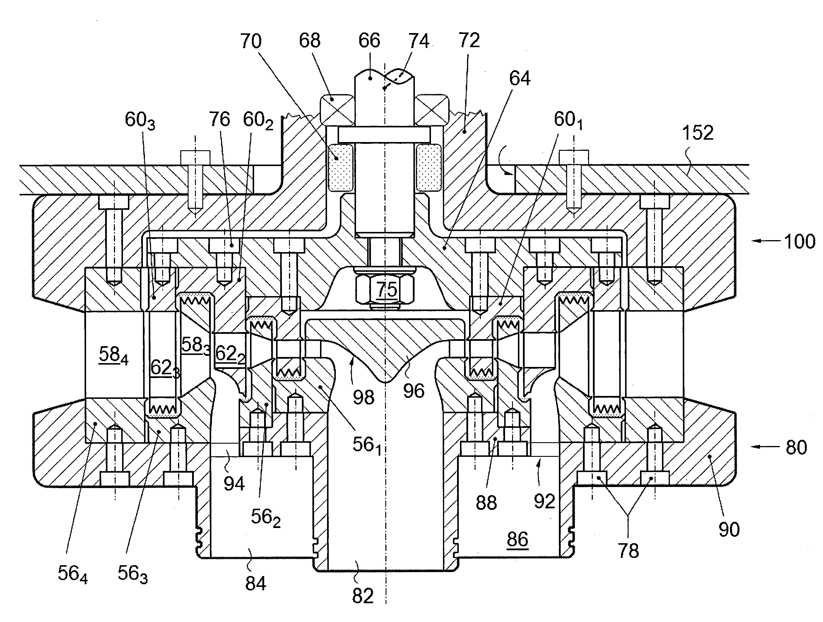
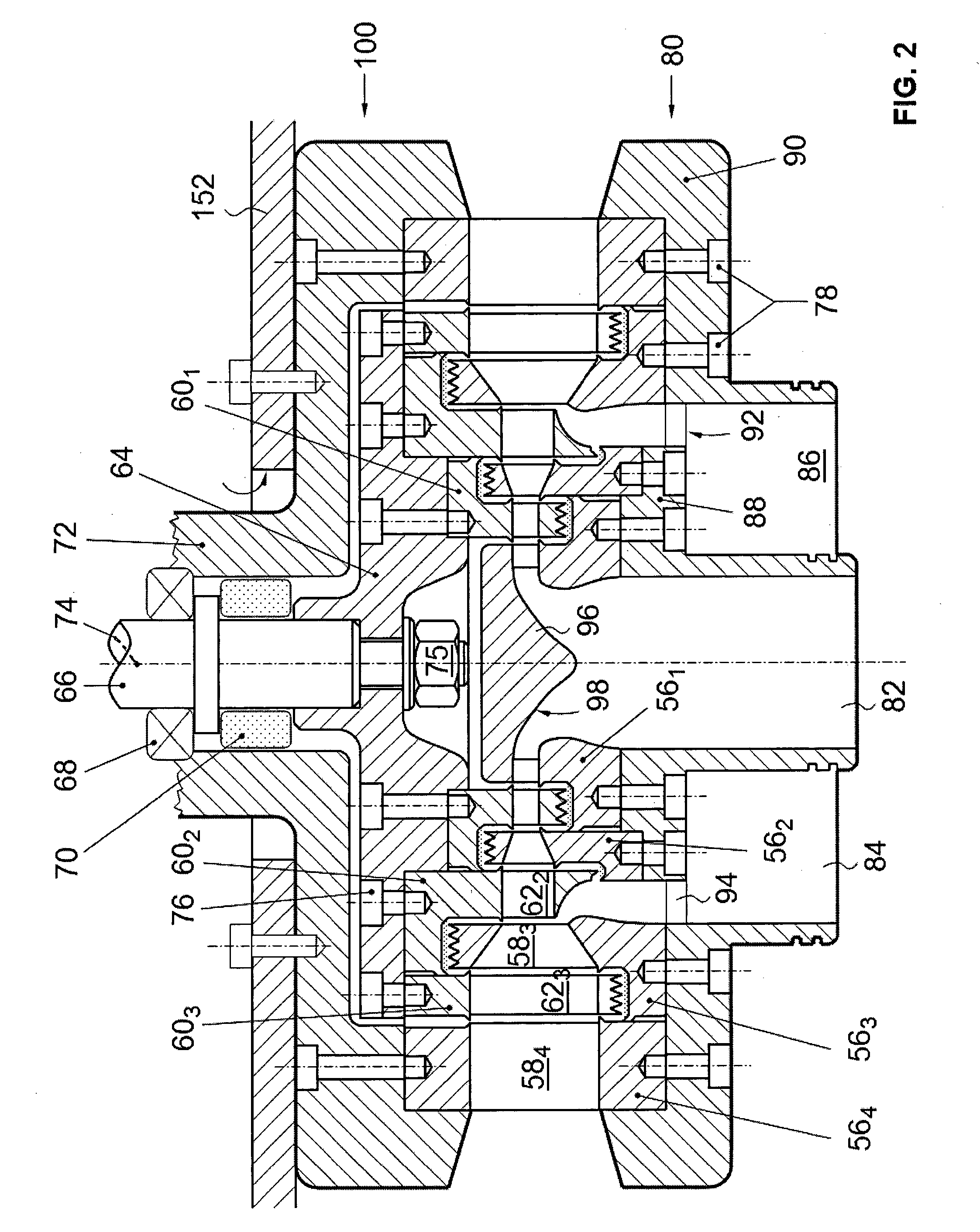
[0032]FIG. 2 is a schematic cross-section through a turbine 16 in accordance with the present invention. It will first be noted that the turbine 16 is a multi-stage (here a three-stage) outward-flow radial type turbine, i.e. the vapour axially enters into the turbine 16 and then flows in a radial direction outward through the different stages of the turbine 16, which are substantially concentric. The turbine is furthermore of the induction type, i.e. a secondary flow of low pressure vapour is induced at a low pressure stage into the turbine 16. Finally, the turbine is of the impulse type, i.e. the vapour is mainly expanded as it passes through the stator of the turbine 16.

[003...


PUM


Abstract

A multi-stage turbine (16) is designed as an induction turbine with vapour induction in at least one intermediary stage. It is more particularly conceived as a radial-outward-flow type multi-stage turbine, with an axial main vapour inlet port (82) and an annular secondary vapour inlet port (84), which is arranged in the turbine (16) so as to annularly induce, in an intermediary stage of said turbine, a secondary vapour stream into an already partially expanded radial main vapour stream. The annular secondary vapour inlet port (84) comprises as a ring-zone (92) with through holes (94), which radially surrounds said axial main vapour inlet port (82) in a first turbine housing part (80). The axial vapour inlet port comprises a first tubular vapour inlet connection (82). The annular vapour inlet port comprises a second tubular vapour inlet connection (84) surrounding the first tubular vapour inlet connection (82), so as to define with the latter an annular space (86), wherein the ring-zone (92) with through holes (94) is arranged in this annular space (86).

Description

TECHNICAL FIELD[0001]The present invention generally relates to a turbine for expanding a pressurized vapour, in particular to a turbine with vapour induction in at least one intermediary turbine stage.BACKGROUND ART[0002]Due to the general necessity to reduce CO2 emissions and to the loss of trust in nuclear power plants, devices for producing electricity with low temperature sources are gaining of importance. Low temperature sources include e.g. industrial waste heat, low temperature geothermal heat sources, low temperature biomass energy and low temperature solar energy, but also novel low temperature heat generators based on chemical or nuclear reactions.[0003]Such devices generally work according to a so-called Organic Rankine Cycle (ORC), i.e. a Rankine cycle in which the working fluid is an organic fluid with a lower evaporation temperature than water. The working principle underlying the ORC is basically the same as that of the classical Rankine cycle in which the working fl...

Claims


Application Information

Patent Timeline
IPC IPC(8): F01D5/04
CPCF01D5/04F01D1/28F01D5/041
Inventor MA TREJEAN, LUC
Owner EQUITHERM S A R L
Why Eureka
Try Eureka