Wire electrical discharge machining device

An electrical discharge machining and wire technology, applied in the field of wire electrical discharge machining devices, can solve the problems of wire electrode WE tension fluctuation, hindering wire discharge accuracy and other problems

Active Publication Date: 2020-11-24
SODICK CO LTD
View PDF7 Cites 0 Cited by
  • Summary
  • Abstract
  • Description
  • Claims
  • Application Information

AI Technical Summary

Problems solved by technology

This undesired behavior of the wire electrode WE causes the tension of the wire electrode WE to fluctuate, which is a factor that hinders the accuracy of wire electric discharge machining.

Method used


Image

  • Wire electrical discharge machining device
  • Wire electrical discharge machining device
  • Wire electrical discharge machining device

Examples


Embodiment Construction

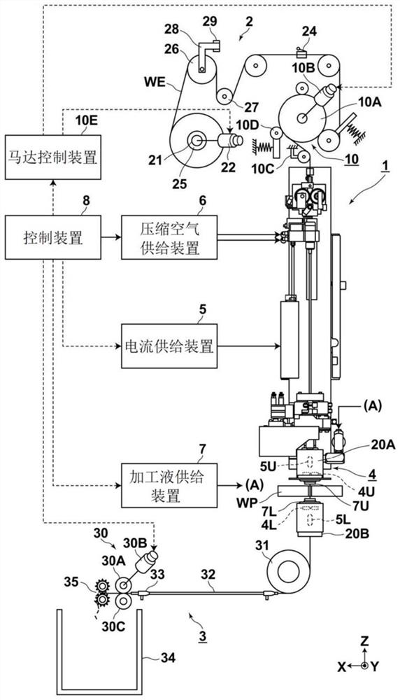
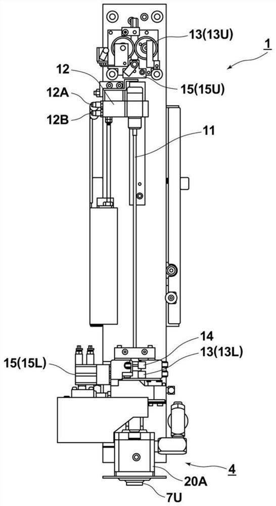
[0061] Hereinafter, embodiments of the present invention will be described with reference to the drawings. figure 1 It is a figure which shows the 1st Embodiment of the electric wire electric discharge machining apparatus of this invention. exist figure 1 In , a wire electric discharge machining device is schematically shown so as to make the predetermined travel path of the wire electrode clear. exist figure 1 In the figure, the automatic splicing device, wire supply mechanism, and wire guide mechanism are shown as viewed from the front of the machine, and the wire collection mechanism is shown as viewed from the side of the machine. Below, refer to figure 1 and figure 2 , and the configuration of the electric wire electric discharge machining device according to this embodiment will be described.

[0062] The wire electrode WE and the workpiece WP are arranged to face each other so that a predetermined machining gap is formed between the wire electrode WE and the w...


PUM


Abstract

In a wire electrical discharge machining device, a wire electrode released from a wire bobbin can be supplied toward a wire electrical discharge machining portion without generating permanently bending or twisting. A first pulley26, which receives a wire electrode WE fed out from a wire bobbin 25 and delivers the wire electrode to the downstream side, is disposed to wind the wire electrode WE to afirst delivery position 61 of an outer peripheral portion opposite to a first reception position 60 across a central portion in a radial direction and deliver the wire electrode WE downward. The first pulley 26 is swingable in the horizontal direction with one end in the radial direction as a fulcrum. The swing fulcrum is disposed, in the width direction of the wire bobbin25, within a range fromone end to the other end in the width direction of the wire bobbin25.

Description

technical field [0001] The invention relates to a wire electric discharge processing device. Background technique [0002] In the past, in Figure 7 In the electric discharge machining device of cited document 1 shown, when the angle of entry θ with respect to the pulley 41 is relatively small, the winding path of the wire electrode WE can be smoothly unwound by accurately retracing the path when the winding is formed. However, when the entry angle θ is relatively large where the wire electrode WE is unwound near the end of the wire bobbin 25, the wire electrode WE cannot be unwound smoothly. This is because the wire electrode WE stretched so as to be unwound from the wire bobbin 25 may move so as to reach another place over the wire electrode WE wound inside it. Such undesired behavior of the wire electrode WE causes the tension of the wire electrode WE to fluctuate, which is a factor that hinders the accuracy of the wire electric discharge machining. [0003] As a config...

Claims


Application Information

Patent Timeline
Patent Type & Authority Applications(China)
IPC IPC(8): B23H1/00B23H11/00
CPCB23H1/00B23H11/00B23H7/10
Inventor 保坂昭夫
Owner SODICK CO LTD
Why Eureka
Try Eureka