Teapot glazing device
A technology of teapots and support columns, applied in the field of glazing devices, to achieve the effect of reducing manual operations
- Summary
- Abstract
- Description
- Claims
- Application Information
AI Technical Summary
Problems solved by technology
Method used
Image

Examples
Embodiment 1
[0040] A teapot glazing device such as figure 1 As shown, it includes a base 1, a first support column 2, a disc 3, a glaze bucket 4, a water bucket 5, a rotating mechanism 6 and a pressing mechanism 7, and the base 1 is uniformly provided with a first support column 2, and the first support column 2 There is a disk 3 on the top, a glaze bucket 4 and a water bucket 5 are placed on the right of the base 1, the water bucket 5 is located behind the glaze bucket 4, a rotating mechanism 6 is installed in the middle of the base 1, and a pressing mechanism is installed on the top and bottom of the disk 3 7.
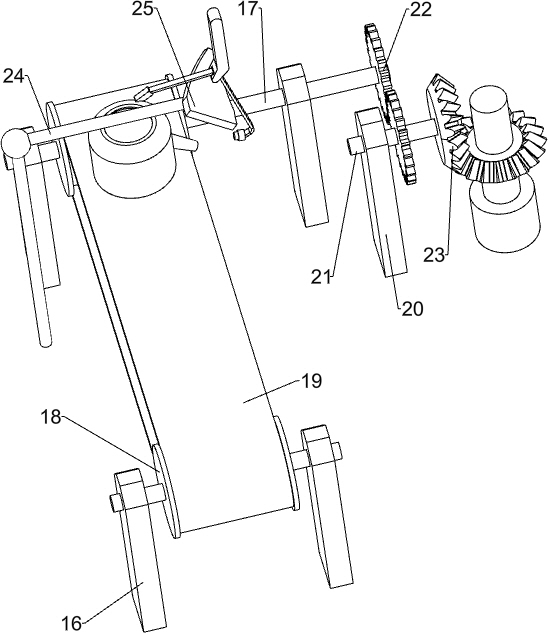
[0041]When the teapot needs to be glazed, the teapot is manually clamped on the parts of the rotating mechanism 6, and the parts of the rotating mechanism 6 are blocked by the spout, and then the parts of the pressing mechanism 7 are started, and the parts of the pressing mechanism 7 follow Moving down, the parts of the rotating mechanism 6 drive the teapot directly above the g...
Embodiment 2
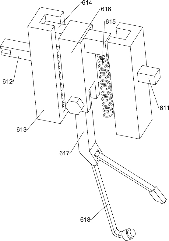
[0043] according to Figure 2-5 As shown, the rotating mechanism 6 includes a second support column 61, a first guide rail piece 62, a third support column 63, a second guide rail piece 64, a fourth support column 65, a third guide rail piece 66, a fifth support column 67, a Four guide rail pieces 68, main shaft 69, round block 610, first slide block 611, second slide block 612, slide rail 613, third slide block 614, first elastic member 615, N-shaped block 616, bent bar 617, clip 618, connecting rod 619, ratchet 620, slide box 621, ratchet 622 and the second elastic member 623, the second support column 61 is evenly provided with on the base 1, the first guide rail sheet 62 is installed on the top of the second support column 61, circular The bottom of the disk 3 is evenly provided with a third support column 63, the bottom of the third support column 63 is connected with a second guide rail piece 64, the second guide rail piece 64 is located directly above the first guide ra...
Embodiment 3
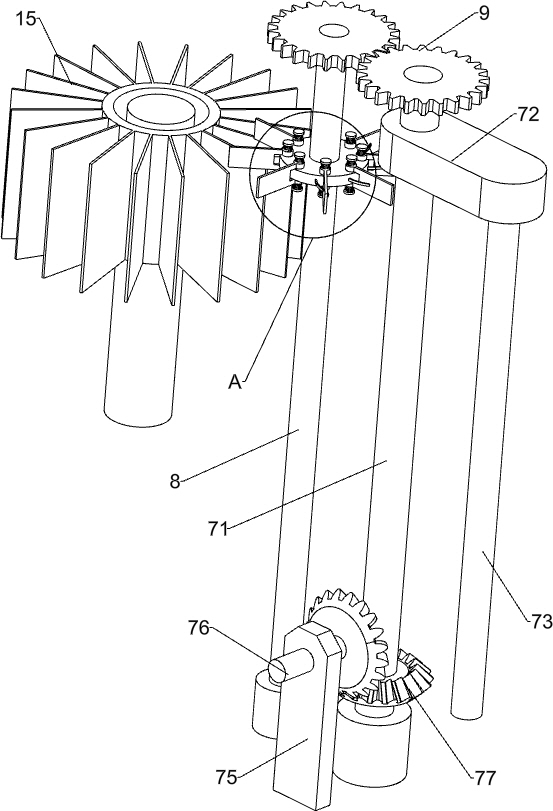
[0048] Specifically, such as Figure 5-7 As shown, it also includes a second screw rod 8, a first circular gear 9, a connecting block 10, a connecting shaft 11, a protrusion 12, a plectrum 13, an elastic piece 131, a third elastic member 14 and a blade cylinder 15, the circle The top right front side of the disc 3 is rotated to be provided with a second screw mandrel 8, and the second screw mandrel 8 and the first screw mandrel 71 top are equipped with a first round gear 9, and the two first round gears 9 are meshed, and the second screw mandrel 8. A connecting block 10 is arranged on the upper part, and a connecting shaft 11 is evenly arranged on the connecting block 10. The upper and lower ends of the connecting shaft 11 are equipped with bumps 12. The middle part of the connecting shaft 11 is provided with a paddle 13. There is an elastic piece 131, and the elastic piece 131 is in contact with the plectrum 13. A third elastic piece 14 is arranged between the bumps 12 on the...
PUM
 Abstract
Description
Claims
Application Information