Safe grouting vibration equipment

A technology for safes and equipment, applied in auxiliary molding equipment, clay preparation devices, supply devices, etc., can solve the problems of easy agglomeration of concrete, uneven grouting, poor filling effect, etc., and achieve uniform grouting, uniform grouting, Simple operation effect

Active Publication Date: 2020-11-24
裘士兴
View PDF6 Cites 2 Cited by
  • Summary
  • Abstract
  • Description
  • Claims
  • Application Information

AI Technical Summary

Problems solved by technology

[0004] The purpose of the present invention is to solve the disadvantages of the existing safe, which tends to cause uneven grouting, and the concrete tends to agglomerate during grouting, resulting in poor filling effect, and proposes a safe Grouting vibration equipment

Method used


Image

  • Safe grouting vibration equipment
  • Safe grouting vibration equipment
  • Safe grouting vibration equipment

Examples


Embodiment 1

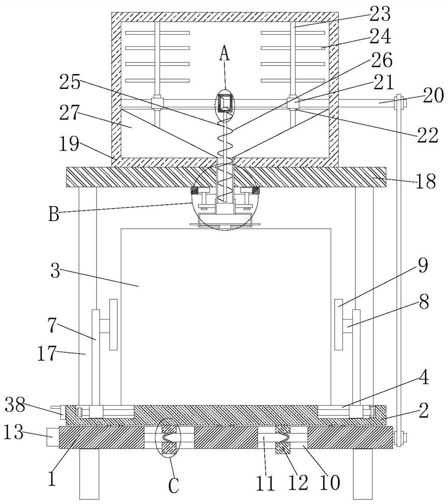
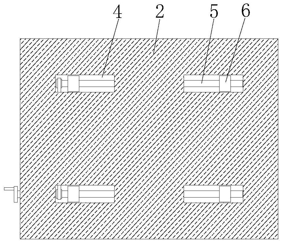
[0029] refer to Figure 1-5 , a safe grouting vibrating device, comprising a base 1, the top of the base 1 is slidably connected with a placement plate 2, and the top of the placement plate 2 is provided with four symmetrically arranged moving slots 4, and the corresponding two moving slots 4 are rotationally connected The first rotating shaft 5 is the same, and the moving block 6 is slidably connected in the moving groove 4. The first rotating shaft 5 is provided with two reverse threads, and the two moving blocks 6 are screwed to the same first rotating shaft 5. The first One end of the rotating shaft 5 is fixedly equipped with a turntable 38, and the two first rotating shafts 5 are connected by transmission. The safe body 3 is placed on the placement plate 2, and the base 1 is provided with two symmetrically arranged sliding holes 10. Inside the two sliding holes 10 The same first rotating rod 11 is rotationally connected, and a motor 13 is fixedly installed on the left sid...

Embodiment 2

[0040] refer to Figure 1-5 , a safe grouting vibrating device, comprising a base 1, the top of the base 1 is slidably connected with a placement plate 2, and the top of the placement plate 2 is provided with four symmetrically arranged moving slots 4, and the corresponding two moving slots 4 are rotationally connected The first rotating shaft 5 is the same, and the moving block 6 is slidably connected in the moving groove 4. The first rotating shaft 5 is provided with two reverse threads, and the two moving blocks 6 are screwed to the same first rotating shaft 5. The first One end of the rotating shaft 5 is welded with a turntable 38, the two first rotating shafts 5 are connected by transmission, the safe body 3 is placed on the placement plate 2, and the base 1 is provided with two symmetrically arranged sliding holes 10, and the two sliding holes 10 rotate The same first rotating rod 11 is connected, the left side of the base 1 is fixed with a motor 13 by bolts, the output ...


PUM


Abstract

The invention belongs to the technical field of grouting vibration, and particularly relates to safe grouting vibration equipment. According to the problem that when an existing safe is grouted, the safe is prone to be grouted unevenly, concrete is prone to agglomerating during grouting, and the filling effect is poor, the following scheme is proposed. The equipment includes a base, a placing plate is connected with the top of the base, four moving grooves are formed in the top of the placing plate, a same first rotating shaft is connected in two corresponding moving grooves in a rotating mode, and moving blocks are connected in the moving grooves in a sliding mode, two reverse threads are arranged on the first rotating shafts, two moving blocks are connected with the same first rotating shaft in a threaded mode, turntables are mounted at one ends of the first rotating shafts, and two first rotating shafts are connected in a transmission mode, a safe body is placed on the placing plate, and two sliding holes are formed in the base. According to the equipment, the operation is simple, the usage is convenient, a safe can be clamed and fixed, meanwhile the safe can be vibrated and grouted evenly, and the equipment is used by people conveniently.

Description

technical field [0001] The invention relates to the technical field of grouting vibration, in particular to a safe grouting vibration device. Background technique [0002] Due to the customer's emphasis on safety performance, key parts will be reinforced during the design and manufacture of safes, and different customers and different levels of safes also have different requirements for cement formulations, both of which will cause concrete to flow during the grouting process It is not smooth, and there is a risk that some areas are not filled with concrete, and the concrete grouting is an important process that is completed in a short time. If the safe is partially not filled with concrete, there will be serious quality problems, which will affect both the customer and the manufacturer. would cause serious damage. [0003] When the existing safe is grouted, it is easy to cause its grouting to be uneven, and the concrete is likely to agglomerate during grouting, resulting i...

Claims


Application Information

Patent Timeline
IPC IPC(8): B28B13/02B28B1/093B28B17/00B28C5/16B28C7/16
CPCB28B1/093B28B13/0235B28B17/00B28C5/0806B28C5/0831B28C5/16B28C7/167
Inventor 罗峰
Owner 裘士兴
Why Eureka
Try Eureka