Pile tip grouting device for multipoint pouring

A technology of grouting device and pile tip, which is applied in the field of post-grouting construction of pile tip and pile side of pile foundation, can solve the problems of uneven grouting, backflow of slurry, no anti-reverse function, etc., achieve uniform grouting, avoid backflow of grout, The effect of simple structure

Pending Publication Date: 2017-12-22
CHINA CONSTR SECOND ENG BUREAU LTD
View PDF0 Cites 2 Cited by
  • Summary
  • Abstract
  • Description
  • Claims
  • Application Information

AI Technical Summary

Problems solved by technology

The existing grouting pipe is only a conveying pipe for single-point grouting to the gap, and has no reverse function, so uneven grouting and backflow of grout are prone to occur during the grouting process

Method used


Image

  • Pile tip grouting device for multipoint pouring
  • Pile tip grouting device for multipoint pouring
  • Pile tip grouting device for multipoint pouring

Examples


Embodiment Construction

[0013] The present invention will be further described in detail through the accompanying drawings and specific embodiments below.

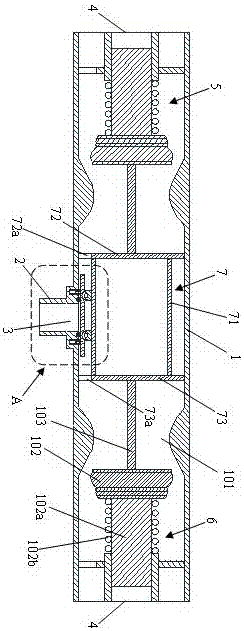
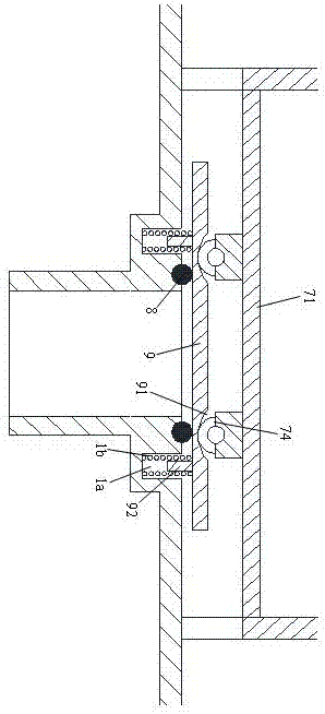
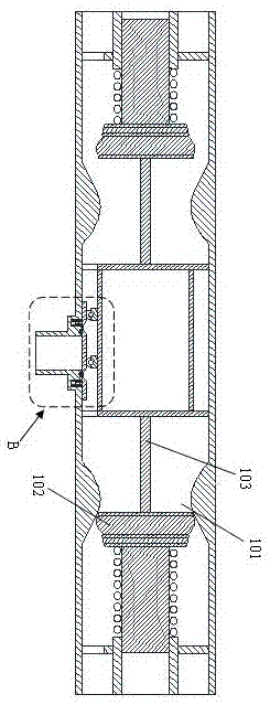
[0014] As shown in the figure, this embodiment provides a pile end grouter for multi-point pouring, which includes a delivery main pipe 200 for delivering slurry, several delivery branch pipes 201 connected to the delivery main pipe 200, connected to the The grouting device on the conveying branch pipe 201, the grouting device includes a pipe body 1, a grout inlet 3 for connecting the grouting pipe 2 is arranged in the middle of the pipe body 1, and at both ends of the pipe body 1 There are two slurry outlets 4, each of which is connected to a slurry outlet 4a, and the ports of the two slurry outlets 4a extend to different positions so that grouting can be carried out to different positions. The slurry outlet 4 is provided with a first one-way valve 5 and a second one-way valve 6, and a piston 7 is provided in the middle of the inside of the pipe...


PUM


Abstract

The invention discloses a pile tip grouting device for multipoint pouring. The pile tip grouting device comprises a conveying master pipe used for conveying slurry, a plurality of conveying branch pipes connected to the conveying master pipe and a grouting device body connected to the conveying branch pipes. The grouting device body comprises a pipe body, a slurry inlet used for being connected with a grouting pipe is formed in the middle of the pipe body, and the two ends of the pipe body are two slurry outlets; each slurry outlet is connected with a slurry outlet pipe, and ports of the two slurry outlet pipes extend to different positions so that grouting can be conducted towards the different positions; and the two slurry outlet pipes are provided with a first one-way valve and a second one-way valve correspondingly. Through the technical scheme, all the conveying branch pipes are inserted in different positions of concrete gaps, the two slurry outlet pipes of the grouting device body connected with all the conveying branch pipes are both inserted in different positions, so that multipoint grouting is achieved, the grouting efficiency is improved, and grouting is more uniform.

Description

technical field [0001] The invention relates to a pile end grouting device for multi-point grouting, which belongs to the technical field of post grouting construction at the pile end and side of a pile foundation. Background technique [0002] The post-grouting technology of cast-in-situ piles has been widely used in the country. It can effectively improve the bearing capacity of cast-in-place piles. Generally, after grouting, the bearing capacity can be increased by more than 25%. At the same time, the quality of the soil bearing layer at the bottom of the piles can be improved to ensure the piles The design bearing capacity is required, but it cannot replace a steel bar in this part. Grouting pipe is a pre-embedded grouting pipe system used for permanent sealing of construction joints, cold joints, pipe seepage joints, gaps between ground walls, etc. in concrete. The main function of the grouting pipe is to help concrete pour into various gaps, so that it can be complete...

Claims


Application Information

Patent Timeline
Patent Type & Authority Applications(China)
IPC IPC(8): E02D15/04
CPCE02D15/04
Inventor 蒋牧王文渊陈江马虔苟浩
Owner CHINA CONSTR SECOND ENG BUREAU LTD
Why Eureka
Try Eureka