Temporary subsea base and method for mass installation of deepwater surface conduits

A technology of template and conduit, which is applied in the direction of drill pipe, casing, earthwork drilling, etc., can solve problems such as low work efficiency, affecting installation accuracy, impacting conduit, etc., and achieves easy maintenance, improved working time, and guaranteed positioning accuracy Effect

Active Publication Date: 2022-07-12
CHINA NAT OFFSHORE OIL CORP +3
View PDF10 Cites 0 Cited by
  • Summary
  • Abstract
  • Description
  • Claims
  • Application Information

AI Technical Summary

Problems solved by technology

For the installation of conduits that require high-precision positioning and depth of entry into the mud, it is recommended to use piling installation on the premise of meeting the requirements in consideration of economy, and there are currently cases in the world that prove that piling installation of conduits has strong technical adaptability in this context Especially for the installation of surface conduits similar to the deepwater tension leg platform oil and gas development mode, it has strict requirements for the arrangement of subsea well grooves, which requires the conduits to have high installation accuracy requirements in the lateral direction, while the prior art usually positions the conduits sequentially After the installation into the mud, the more the number of conduits, the longer the waiting time for the conduits in place to stand on the seabed, the work efficiency is low, and several conduits are easy to hit the adjacent conduits that have been in place due to movement during the process of sequentially positioning the conduits into the mud, resulting in Shifting of the seated conduit, affecting its installation accuracy

Method used


Image

  • Temporary subsea base and method for mass installation of deepwater surface conduits
  • Temporary subsea base and method for mass installation of deepwater surface conduits
  • Temporary subsea base and method for mass installation of deepwater surface conduits

Examples


Embodiment Construction

[0032] In order to have a clearer understanding of the technical features, objects and effects of the present invention, the specific embodiments of the present invention will now be described in detail with reference to the accompanying drawings.

[0033] In the present invention, in order to make the language concise, the conduits mentioned in this article are all deep-water surface conduits, and the bases mentioned are all temporary submarine bases, which will not be repeated in the following.

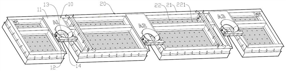
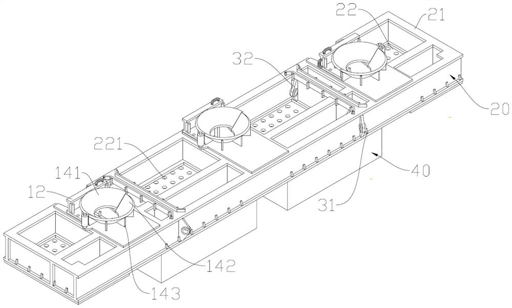
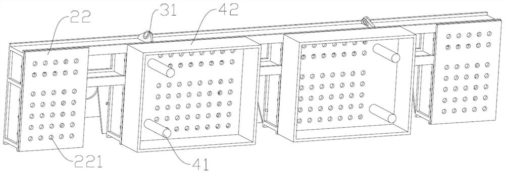
[0034] In the development of deepwater oil and gas fields, multiple deepwater surface conduits need to be installed, and the installation accuracy of the conduits is usually very high. Usually, the conduits need to be positioned and installed in sequence, which is very inefficient, and it is easy to collide during the process of positioning and installing the conduit. Other pipes that have been inserted into the mud will cause the position of the pipes that have been inserted into th...


PUM


Abstract

The invention discloses a temporary subsea base plate and a method for batch installation of deep-water surface conduits, wherein the temporary subsea base plate comprises a plurality of positioning units for positioning and installing deep-water surface conduits at preset positions, and the positioning unit includes a positioning body provided with an opening, The opening includes an open end communicating with the outside world and a closed end arranged in the positioning body. The opening is also provided with a movable bracket detachably connected to the positioning body. The closed end of the opening and the movable bracket are enclosed to form a positioning hole for positioning. The invention uses several positioning units on the temporary seabed base plate to enable several conduits to be installed at the same time, so as to ensure the positioning accuracy, and at the same time, it can also reduce the collision risk caused by the long-term hoisting and moving of the conduit string on the seabed. , so that the temporary subsea base plate and the conduit can be directly separated after the installation work is completed to complete the recovery work, improve the work efficiency, ensure the operation quality, and at the same time, the structure is simple and easy to maintain.

Description

technical field [0001] The invention relates to the field of deepwater oil and gas field development and drilling, in particular to a temporary seabed base plate and a method for installing deepwater surface conduits in batches. Background technique [0002] At present, there are three main methods of batch installation of surface conduits for deepwater oil and gas field development in the industry: drilling method, jetting method and piling method. For the installation of conduits with high-precision positioning and installation requirements for the depth of the mud, the piling method is recommended for installation under the premise that the economy meets the requirements. At present, there are cases around the world that have proved that the installation of conduits by the piling method has strong technical adaptability in this context. Especially for the surface conduit installation similar to the oil and gas development mode of the deepwater tension leg platform, it has...

Claims


Application Information

Patent Timeline
Patent Type & Authority Patents(China)
IPC IPC(8): E21B15/02E21B43/01E21B19/00E21B47/001
CPCE21B15/02E21B43/01E21B19/002
Inventor 韦红术刘正礼邓玉明赵苏文赵维青赵德卢先刚张玉山李鑫李健张星星田瑞瑞严德
Owner CHINA NAT OFFSHORE OIL CORP
Why Eureka
Try Eureka