Staggered-layer supporting structure of piezoelectric micropump and gas control device
A supporting structure and control device technology, applied to parts, pumps, and pump elements of elastic fluid pumping devices, can solve problems such as increasing the volume of piezoelectric pumps, and achieve miniaturization and shrinkage of the circumference effect of size
- Summary
- Abstract
- Description
- Claims
- Application Information
AI Technical Summary
Problems solved by technology
Method used
Image
Examples
Embodiment 1
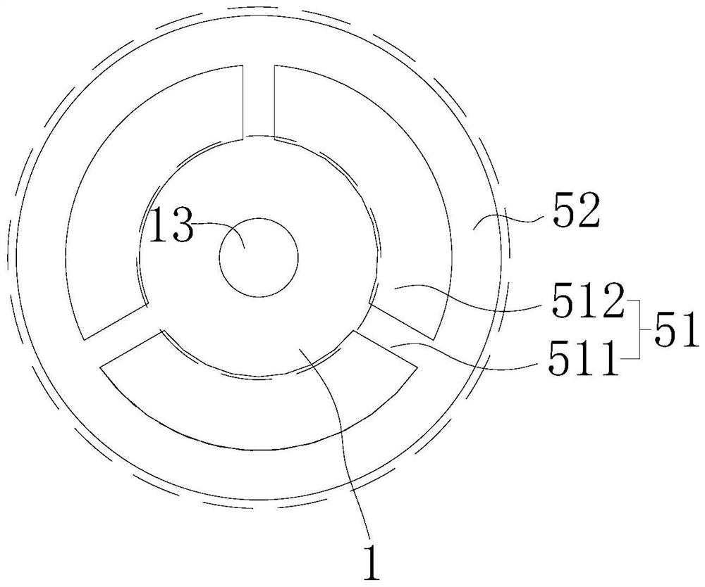
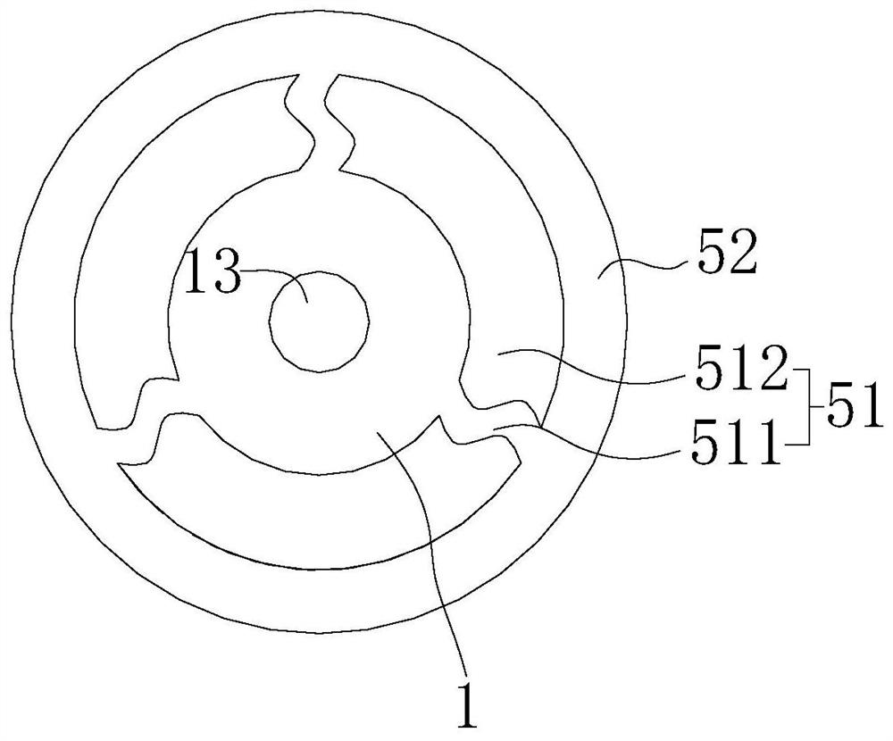
[0067] like Figure 1-23 As shown, the present embodiment provides a staggered support structure of a piezoelectric micropump, including a piezoelectric micropump and a support plate 4, one side of the piezoelectric micropump is connected to the support plate 4, and the piezoelectric micropump and the support plate The gap between 4 forms an air intake cavity 6, and the support plate 4 supports and constrains the piezoelectric micropump from below the piezoelectric micropump. It avoids the disadvantage that the piezoelectric micropump in the prior art is connected to the peripheral supporting part through the connecting part extending in the circumferential direction, and the supporting part is laminated and fixed, which increases the circumferential volume of the piezoelectric micropump.
[0068] The piezoelectric micropump includes a resonance plate 1, a piezoelectric vibrator 2, and an electrode assembly 3. The piezoelectric vibrator 2 includes a vibration plate 21 and a pi...
Embodiment 2
[0086] like Figure 24-27 As shown, this embodiment is basically the same as the first embodiment, the difference is that the protrusion 11 is not directly connected to the supporting plate 4 , but is supported by the supporting plate 4 through the connecting plate 9 .
[0087] In this embodiment, the connection plate 9 is connected to the support plate 4, and the protrusion 11 is connected to the connection plate 9. There is a gap between the connection plate 9 and the support plate 4 to form an air intake transition cavity 42. The connection plate 9 and the resonance plate 1 Together with the protrusion 11, the intake cavity 6 is formed. Specifically, the outer periphery of the supporting plate 4 protrudes to form a concave portion, and the connecting plate 9 is in sealing connection with the outer peripheral protrusion of the supporting plate 4 , so that an air intake transition chamber 42 can be formed between the connecting plate 9 and the supporting plate 4 .
[0088] I...
Embodiment 3
[0095] like Figure 28 As shown, the present embodiment is basically the same as the second embodiment, the difference is that no protrusion is provided on the outer periphery of the supporting plate 4, the connecting plate 9 is connected with the supporting plate 4, and a third protrusion is formed between the connecting plate 9 and the supporting plate 4 43, the third protrusion 43 is annular, the third protrusion 43 can be integrally formed with the support plate 4, and can also be integrally formed with the connecting plate 9, or the third protrusion 43 is set independently, and its two surfaces are respectively connected with the The connection plate 9 is connected to the support plate 4 . In the gas control device, the connection plate 9 can be completely accommodated in the cavity surrounded by the support plate 4 and the housing 7, so that the circumferential dimension of the connection plate 9 can be reduced.
PUM
 Abstract
Description
Claims
Application Information
 - R&D
- Intellectual Property
- Life Sciences
- Materials
- Tech Scout
- Unparalleled Data Quality
- Higher Quality Content
- 60% Fewer Hallucinations
Browse by: Latest US Patents, China's latest patents, Technical Efficacy Thesaurus, Application Domain, Technology Topic, Popular Technical Reports.
© 2025 PatSnap. All rights reserved.Legal|Privacy policy|Modern Slavery Act Transparency Statement|Sitemap|About US| Contact US: help@patsnap.com


