
Sensor fixing device for track detection

A fixing device and track detection technology, which is applied in the direction of railway vehicle shape measuring devices, supporting machines, transportation and packaging, etc., can solve problems such as loosening of fixing frames, deviation of detection results of acoustic emission sensors, and inaccurate damage detection, etc., to achieve Avoid multiple installations and high disassembly efficiency

Active Publication Date: 2020-11-24
ZHENGZHOU RAILWAY VOCATIONAL & TECH COLLEGE
View PDF13 Cites 0 Cited by
  • Summary
  • Abstract
  • Description
  • Claims
  • Application Information

AI Technical Summary

Problems solved by technology

[0003] At present, the acoustic emission sensor is mostly used to detect the damage of the rail. Specifically, the contact of the acoustic emission sensor is used to receive the vibration transmitted by the rail for detection, and the acoustic emission sensor is kept in contact with the rail through the fixing frame, otherwise it will cause the acoustic emission sensor The damage detection of the rail is not accurate, and the existing fixed frame simply fixes the acoustic emission sensor on the rail, and makes the contact of the acoustic emission sensor contact the rail, but it cannot eliminate the transmission of the rail to the fixed frame. Vibration, under long-term vibration, the fixing frame will loosen, which will cause the acoustic emission sensor to be fixed unstable, and the vibration of the rail transmitted to the fixing frame will drive the acoustic emission sensor body to vibrate, so that the vibration of the acoustic emission sensor body offsets a part The contact vibration from the action of the rail to the acoustic emission sensor leads to deviations in the detection results of the acoustic emission sensor; in addition, the traditional fixing frame is inconvenient to apply coupling agent to the contact of the acoustic emission sensor, and it needs to be disassembled and re-applied

Method used


Image

  • Sensor fixing device for track detection
  • Sensor fixing device for track detection
  • Sensor fixing device for track detection

Examples


Embodiment Construction

[0031] The following will clearly and completely describe the technical solutions in the embodiments of the present invention with reference to the drawings in the embodiments of the present invention. Apparently, the described embodiments are only some of the embodiments of the present invention, but not all of them. Based on the embodiments of the present invention, all other embodiments obtained by persons of ordinary skill in the art without making creative efforts belong to the protection scope of the present invention.

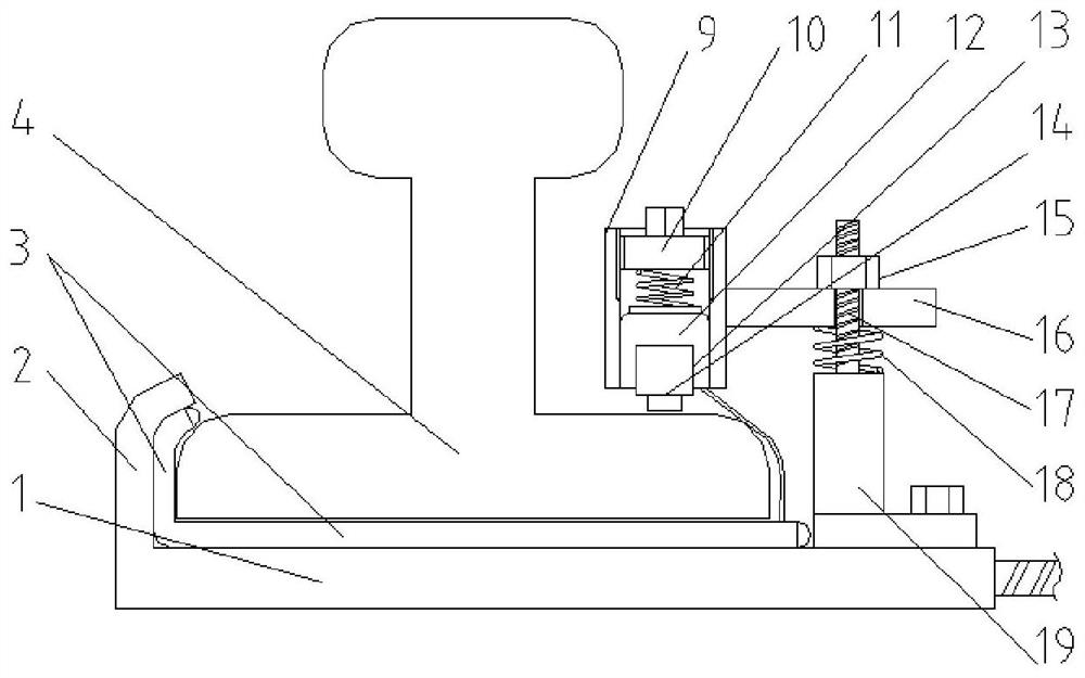
[0032] Such as figure 1 , 2Shown in and 3, as a kind of sensor fixing device that is used for track detection of a preferred embodiment of the present invention, comprises a pair of the base 1 that is respectively arranged on the plate structure below a pair of rails 4 of track, base 1 passes through following The lower ends of the air cushion 3 and the rail 4 are in conflict, and the opposite side between the rails 4 is the inner side, and the opposit...


PUM


Abstract

The invention belongs to the technical field of railway equipment, and particularly discloses a sensor fixing device for track detection. The sensor fixing device for track detection comprises a pairof bases. Clamping grooves are formed in the base so as to be connected with the side edges, located on the outer sides, of the lower ends of steel rails in a clamped mode. The bases are connected through a telescopic mechanism. An installation base is connected with the end, located on the inner side, of each base and connected with a sleeve through a lifting mechanism, the sleeves are verticallyarranged, and the sleeves are located over the side edges, close to the inner sides, of the lower ends of the steel rails. An adjusting bolt, a first stretching spring and an air bag are arranged inan inner hole of each sleeve in sequence from top to bottom, a groove which holds an acoustic emission sensor is formed in the lower end of each air bag, each air bag is connected with an air cushionthrough a pipe, the air cushions are laid in the clamping grooves and the bases, and the clamping grooves and the bases make contact with the steel rails through the air cushions. According to the sensor fixing device for track detection, the vibration of acoustic emission sensor bodies can be effectively eliminated, the situation that the acoustic emission sensors and the steel rails are kept abutting against each other in real time is guaranteed, a coupling agent is conveniently replaced and smeared, and the accuracy of a detection result is ensured.

Description

technical field [0001] The invention relates to the technical field of railway equipment, in particular to a sensor fixing device for rail detection. Background technique [0002] With the development of the times, the current society has entered the era of logistics and passenger flow, and the transportation industry has developed rapidly. While improving the efficiency of railway transportation, it is necessary to ensure the normal operation of railway equipment, especially the rails of the track, which require frequent testing to obtain Whether the rail is damaged or the degree of damage. [0003] At present, the acoustic emission sensor is mostly used to detect the damage of the rail. Specifically, the contact of the acoustic emission sensor is used to receive the vibration transmitted by the rail for detection, and the acoustic emission sensor is kept in contact with the rail through the fixing frame, otherwise it will cause the acoustic emission sensor The damage dete...

Claims


Application Information

Patent Timeline
Patent Type & Authority Applications(China)
IPC IPC(8): F16M11/04F16M13/02F16F15/023F16F15/04F16F15/067B61K9/10
CPCB61K9/10F16F15/0232F16F15/046F16F15/067F16M11/04F16M13/02
Inventor 刘成李正辉金光陈享成黄根岭
Owner ZHENGZHOU RAILWAY VOCATIONAL & TECH COLLEGE
Learn More