Distributed optical fiber sensing system

A distributed optical fiber and sensing system technology, which is applied in the direction of transmitting sensing components, converting sensor output, and instruments by using optical devices, and can solve the problems of reduced energy of scattered light signals, impact on accuracy, and inability to achieve long-distance detection.

Active Publication Date: 2020-11-24
STATE GRID HEBEI ELECTRIC POWER CO LTD +1
View PDF6 Cites 4 Cited by
  • Summary
  • Abstract
  • Description
  • Claims
  • Application Information

AI Technical Summary

Problems solved by technology

[0003] The purpose of the present invention is to provide a distributed optical fiber sensing system, which aims to solve the problem that with the increase of distance, the energy of the feedback scattered light signal decreases sharply, which has a great impact on accuracy and cannot realize long-distance detection.

Method used


Image

  • Distributed optical fiber sensing system
  • Distributed optical fiber sensing system
  • Distributed optical fiber sensing system

Examples


Embodiment Construction

[0022] In order to make the technical problems, technical solutions and beneficial effects to be solved by the present invention clearer, the present invention will be further described in detail below in conjunction with the accompanying drawings and embodiments. It should be understood that the specific embodiments described here are only used to explain the present invention, not to limit the present invention.

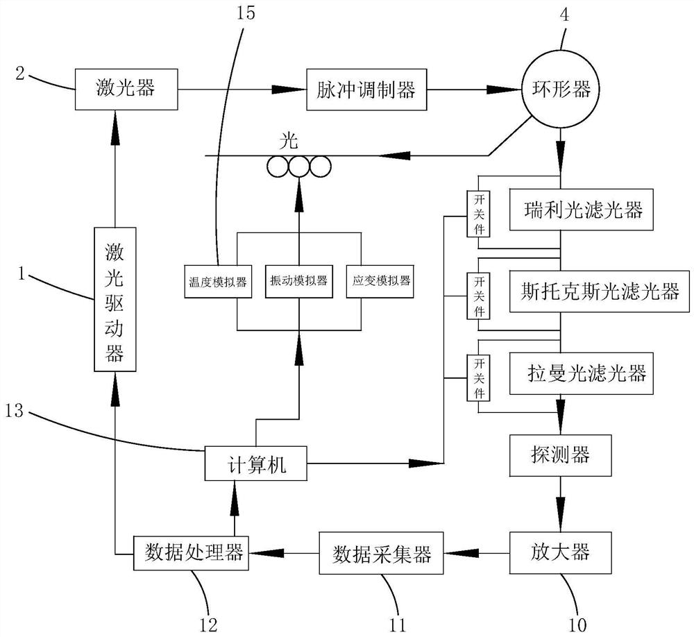
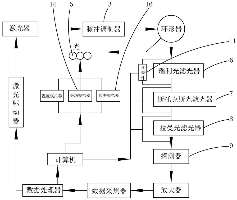
[0023] see figure 1 and figure 2 , the distributed optical fiber sensing system provided by the present invention will now be described. Distributed fiber optic sensing system including light source, filter and multiple test boxes. The output end of the light source is connected with a pulse modulator 3, the output end of the pulse modulator 3 is connected with a circulator 4, the first port of the circulator 4 is connected with an optical fiber 5, the second port of the circulator 4 is connected with a coupler, and the coupler The output end of the signal proc...


PUM


Abstract

The invention provides a distributed optical fiber sensing system, which belongs to the technical field of optical fiber measurement and comprises a light source, an optical filter and a plurality oftest boxes; the plurality of test boxes connected with a computer are arranged at intervals along the length direction of the optical fiber, and the test boxes are used for changing the temperature, vibration and strain of the optical fiber; the computer is used for transmitting signal information and the positions of the plurality of test boxes through a signal processor, and simulating a plurality of distributed curves when the value of a single parameter in the corresponding temperature, vibration and strain on the whole length of the optical fiber changes, and determining a fault curve containing an actual fault point and a corresponding fault value according to the plurality of related distributed curves. According to the distributed optical fiber sensing system provided by the invention, the fault curve is determined according to the plurality of distributed curves, and then the fault value corresponding to the parameter in the fault curve is calculated, so that the problem thatthe scattered light signal information obtained by feedback is inaccurate due to relatively long optical fiber length can be avoided, and the data accuracy is further ensured.

Description

technical field [0001] The invention belongs to the technical field of optical fiber measurement, and more specifically relates to a distributed optical fiber sensing system. Background technique [0002] Distributed fiber optic sensing systems are mainly used in industries such as transportation, construction, electric power, coal mines and petrochemicals, and their function is to measure various parameters of these important places in real time. It plays an important role in ensuring the normal operation of industrial system equipment and ensuring the safety of life and property. In the existing method, the energy of the feedback scattered light signal decreases sharply with the increase of the distance, which has a great impact on the accuracy and cannot realize long-distance detection. Contents of the invention [0003] The purpose of the present invention is to provide a distributed optical fiber sensing system, aiming at solving the problem that the energy of the fe...

Claims


Application Information

Patent Timeline
Patent Type & Authority Applications(China)
IPC IPC(8): G01D18/00G01D5/353
CPCG01D18/00G01D5/35358G01D5/35361G01D5/35364
Inventor 杨会峰魏勇张志钦尚立苏汉魏肖明刘玮穆春宇孟显季名扬聂盛阳刘辛彤李英敏
Owner STATE GRID HEBEI ELECTRIC POWER CO LTD
Why Eureka
Try Eureka