
Roller UT flaw detection mechanism and roller flaw detection method thereof

A technology of rollers and manipulators, which is applied to the analysis of solids using sound waves/ultrasonic waves/infrasonic waves, material analysis using sound waves/ultrasonic waves/infrasonic waves, and measuring devices. To solve problems such as the efficiency of sub-flaw detection, to reduce equipment investment and use costs, improve efficiency, and improve the efficiency of flaw detection

Pending Publication Date: 2020-11-24
南通辰同智能科技有限公司
View PDF0 Cites 1 Cited by
  • Summary
  • Abstract
  • Description
  • Claims
  • Application Information

AI Technical Summary

Problems solved by technology

[0002] Roller UT flaw detection is a method that uses ultrasonic energy to penetrate deep into the roller, and when it passes from one section to another, it reflects at the edge of the interface to inspect the internal defects of the roller. When the ultrasonic beam passes from the roller The surface is connected from the probe to the inside of the metal. When a defect is encountered, a reflected wave is generated, and a pulse waveform is formed on the fluorescent screen. According to these pulse waveforms, the position and size of the internal defect of the roller are judged. During the roller UT flaw detection process, on the one hand, it needs to be adjusted The spatial position of the UT probe ensures that the ultrasonic waves emitted by the UT probe maintain a suitable coverage area on the surface of the roller, thereby ensuring the effect of the UT probe on the internal flaw detection of the roller. Move to ensure the integrity of the flaw detection inside the roller. However, in the existing technology, the adjustment of the spatial position of the UT probe and the moving structure are relatively complicated, which not only affects the speed of the adjustment of the UT probe, reduces the efficiency of the roller flaw detection, but also increases equipment investment. and cost of use

Method used


Image

  • Roller UT flaw detection mechanism and roller flaw detection method thereof
  • Roller UT flaw detection mechanism and roller flaw detection method thereof
  • Roller UT flaw detection mechanism and roller flaw detection method thereof

Examples


Embodiment 1

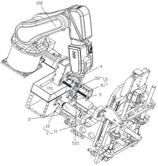
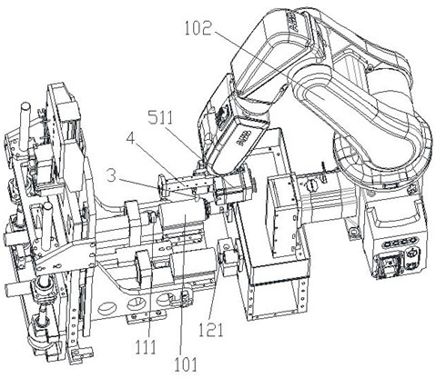
[0022] Such as Figure 1 to Figure 2 It is a specific implementation of this embodiment, applied to the flaw detection roller 101, and its structure includes a manipulator 102, and its structure also includes a clamping assembly 1 that clamps the roller 101 for rotation, a V-shaped groove 2 for placing the roller, and The UT probe 3 and the V-groove 2 can be moved up and down and arranged under the connecting line of the two clamping surfaces of the clamping component 1. The manipulator 102 is provided with a fixed frame 4, and the UT probe 3 is movably arranged on the fixed frame 4. The fixed frame 4 is provided with a drive assembly 5 that drives the UT probe 3 to move on the fixed frame 4. When the manipulator 102 drives the fixed frame 4 to move to the top of the V-shaped groove 2, the UT probe 3 is positioned at the positive end of the roller 101 in the longitudinal direction. Above, the driving assembly 5 drives the UT probe 3 to move on the fixed frame 4 along the lengt...

Embodiment 2

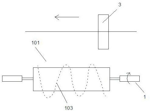
[0030] Such as image 3 As shown, this embodiment provides a roller UT flaw detection mechanism flaw detection roller method, using the principle of the roller UT eye mechanism flaw detection roller in Embodiment 1, the specific steps of the roller flaw detection are as follows: 1. Put the roller 101 Placed on the V-shaped groove 2, 2. The clamping component 1 clamps the roller 101, and moves the V-shaped groove 2 downward, so that the roller 101 is suspended and clamped on the clamping component 1. 3. The manipulator 102 drives The fixed frame 4 moves to the top of the V-shaped groove 2, and the spatial position of the UT probe 3 above the roller 101 is reasonably adjusted by moving the fixed frame 4. On the one hand, keep the bottom of the UT probe 3 and one end of the roller 101 in the length direction at 18mm-22mm. 4. When the clamping component 1 clamps the roller 101 for continuous rotation, the driving component 5 synchronously drives the UT probe 3 on the fixed frame 4...

Embodiment 3

[0033] Such as Figure 4 As shown, the present invention provides a roller UT flaw detection mechanism flaw detection roller method, using the roller UT eye mechanism flaw detection roller principle of embodiment 1, the specific steps of the roller flaw detection are as follows: 1. Place the roller 101 On the V-shaped groove 2, 2. The clamping component 1 clamps the roller 101, and moves the V-shaped groove 2 downward, so that the roller 101 is suspended and clamped on the clamping component 1. 3. The manipulator 102 drives and fixes it The frame 4 moves to the top of the V-groove 2, and the space position of the UT probe 3 above the roller 101 is reasonably adjusted by moving the fixed frame 4. On the one hand, the UT probe 3 is located directly above one end of the roller 101 in the length direction, and on the other hand Keep the bottom of the UT probe 3 and one end of the roller 101 in the length direction at 18mm-22mm. 4. When the clamping assembly 1 rotates the roller 10...


PUM


Abstract

The invention discloses a roller UT flaw detection mechanism and a roller flaw detection method thereof, and is applied to flaw detection of a roller; the mechanism also structurally comprises a clamping assembly for clamping the roller to rotate, a V-shaped groove for placing the roller, and a UT probe. The V-shaped groove is formed below the connecting line of the two clamping surfaces of the clamping assembly in a manner of moving up and down; a fixed frame is arranged on a mechanical arm, and the UT probe is movably arranged on the fixed frame; a driving assembly for driving the UT probe to move on the fixed frame is arranged on the fixed frame; the mechanical arm drives the fixed frame to move to the upper part of the V-shaped groove, so the UT probe is positioned right above one endof the roller in the length direction; the driving assembly drives the UT probe to move on the fixed frame in the length direction of the roller, and the UT probe is electrically connected with a flawdetection fluorescent screen. According to the roller UT flaw detection mechanism, the spatial position of the UT probe above the roller can be flexibly adjusted, the requirement of roller flaw detection is met, the equipment investment and the use cost are reduced, and meanwhile, the flaw detection efficiency of the roller is improved.

Description

Technical field: [0001] The invention relates to the technical field of roller flaw detection equipment manufacturing, in particular to a roller UT flaw detection mechanism and a roller flaw detection method thereof. Background technique: [0002] Roller UT flaw detection is a method that uses ultrasonic energy to penetrate deep into the roller, and when it passes from one section to another, it reflects at the edge of the interface to inspect the internal defects of the roller. When the ultrasonic beam passes from the roller The surface is connected from the probe to the inside of the metal. When a defect is encountered, a reflected wave is generated, and a pulse waveform is formed on the fluorescent screen. According to these pulse waveforms, the position and size of the internal defect of the roller are judged. During the roller UT flaw detection process, on the one hand, it needs to be adjusted The spatial position of the UT probe ensures that the ultrasonic waves emitte...

Claims


Application Information

Patent Timeline
Patent Type & Authority Applications(China)
IPC IPC(8): G01N29/04G01N29/265
CPCG01N29/04G01N29/265G01N2291/0289G01N2291/269
Inventor 许滨
Owner 南通辰同智能科技有限公司
Learn More