Bias voltage control method and system for an optical IQ modulator
An IQ modulator and bias voltage technology, applied in the field of communication, can solve the problem of difficult to meet the requirements of high precision, and achieve the effect of accurate bias voltage
- Summary
- Abstract
- Description
- Claims
- Application Information
AI Technical Summary
Problems solved by technology
Method used
Image
Examples
Embodiment Construction
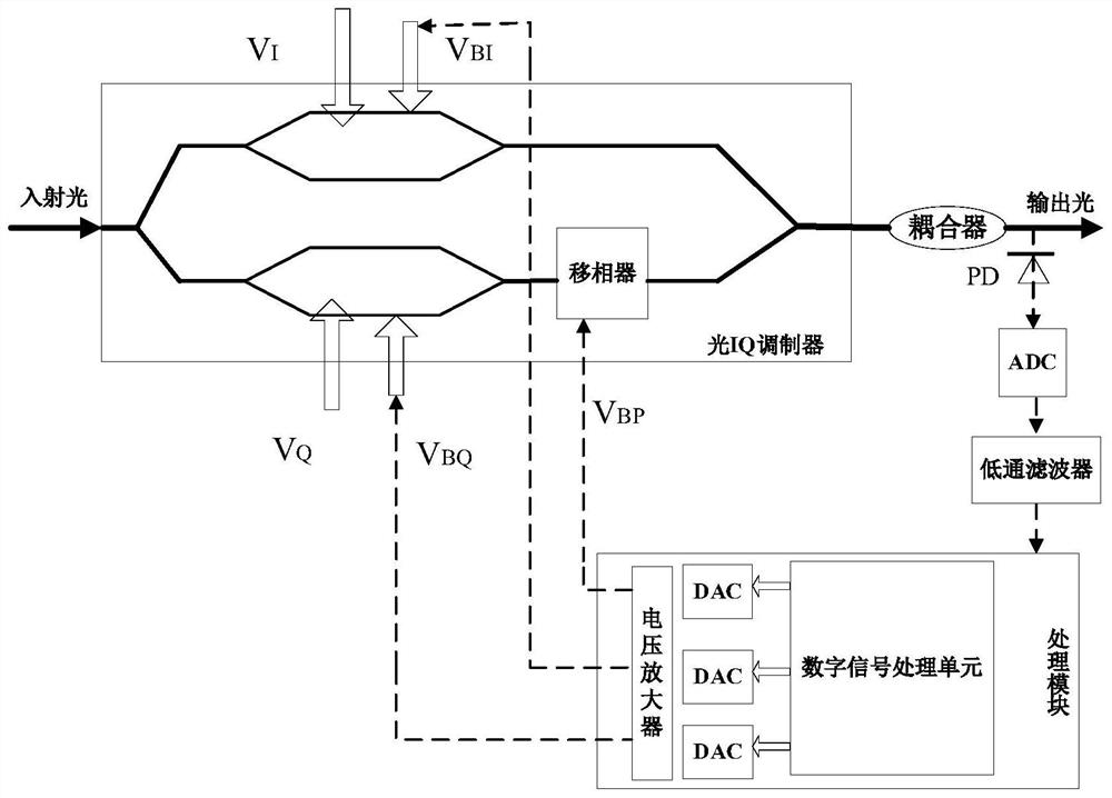
[0046] The present invention will be described in further detail below in conjunction with the accompanying drawings and specific embodiments.
[0053] E
[0054]
[0056]
[0059]
[0061]
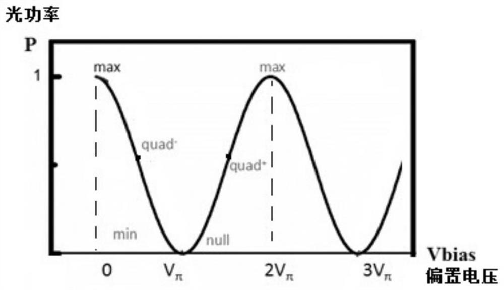
[0066] (1) The phase shifter is at the Quad point (1 / 4 period point), that is, when cos(π / 2)=0.
[0067] (2) The I road and the Q road are located at the Null point, that is, the zero point of the output optical power curve P / V. is actually V
[0069]
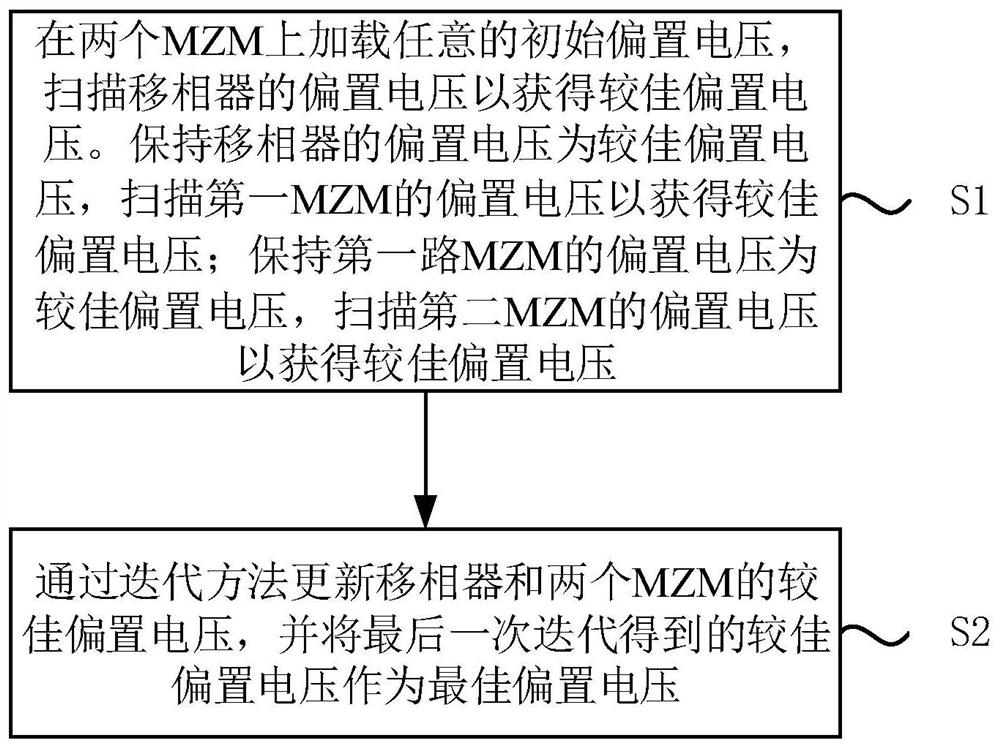
[0075] The number of iterations is determined according to the actual situation, for example, the number of iterations n=5.
[0076] The embodiment of the present invention does not require an external RF driving voltage signal, nor does it require a DC bias voltage on the optical IQ modulator
[0088] In one embodiment, the first MZM is a 1-way MZM, and the second MZM is a Q-way MZM.
[0090] S141: set the I circuit bias voltage as V
[0091] S142: set the bias voltage of the phase shifter as V
[0093] In another embodiment, the first MZM is...
PUM
 Abstract
Description
Claims
Application Information
 - R&D
- Intellectual Property
- Life Sciences
- Materials
- Tech Scout
- Unparalleled Data Quality
- Higher Quality Content
- 60% Fewer Hallucinations
Browse by: Latest US Patents, China's latest patents, Technical Efficacy Thesaurus, Application Domain, Technology Topic, Popular Technical Reports.
© 2025 PatSnap. All rights reserved.Legal|Privacy policy|Modern Slavery Act Transparency Statement|Sitemap|About US| Contact US: help@patsnap.com


