
Bias voltage control method and system of optical IQ modulator

An IQ modulator and bias voltage technology, applied in the field of communication, can solve the problem of difficult to meet the requirements of high precision, and achieve the effect of accurate bias voltage

Active Publication Date: 2020-11-24
FENGHUO COMM SCI & TECH CO LTD
View PDF15 Cites 0 Cited by
  • Summary
  • Abstract
  • Description
  • Claims
  • Application Information

AI Technical Summary

Problems solved by technology

[0005] The conventional bias voltage control method superimposes the low-frequency disturbance signal on the DC bias voltage, extracts the first harmonic component or the second harmonic component of the low-frequency disturbance signal through the closed-loop feedback control circuit, and performs corresponding The advanced digital closed-loop feedback processing realizes the automatic control of the bias voltage, and it is difficult to meet the high-precision requirements in practical applications.

Method used


Image

  • Bias voltage control method and system of optical IQ modulator
  • Bias voltage control method and system of optical IQ modulator
  • Bias voltage control method and system of optical IQ modulator

Examples


Embodiment Construction

[0046] The present invention will be further described in connection with the accompanying drawings and specific examples.

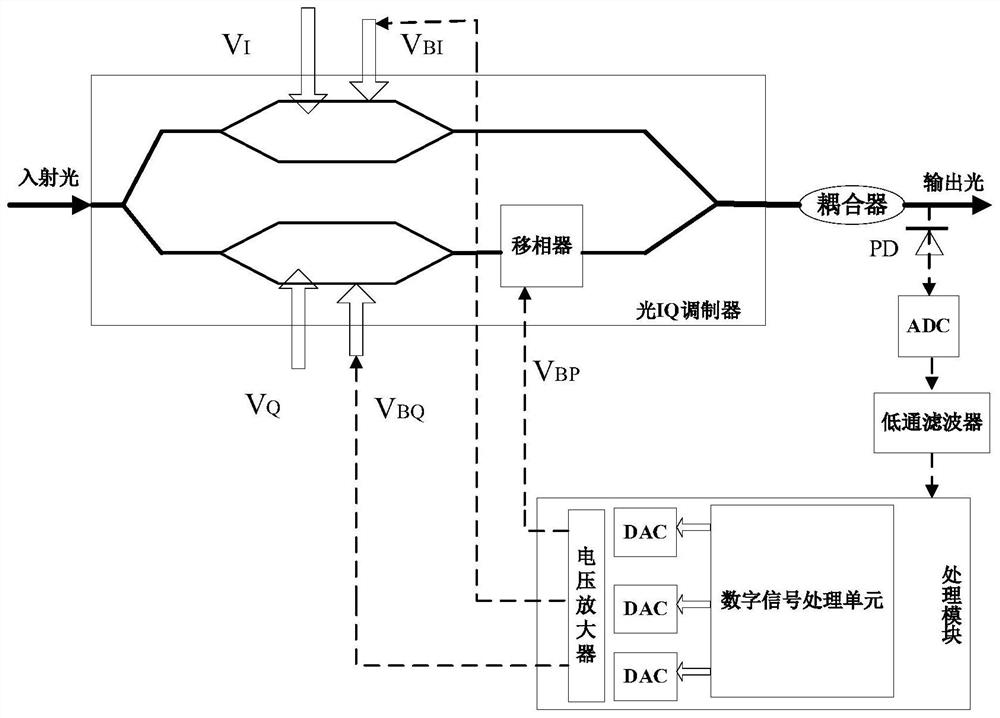
[0047] figure 1 A schematic view of application of the optical bias voltage control system of the IQ modulator of the embodiment of the present invention, wherein the optical IQ modulator comprising two Mach - Zehnder modulators (Mach-Zehnder Modulator, MZM), and a phase shifter (PhaseShifter, PM), two MZM are I and Q channel MZM MZM. Closed loop feedback control of the optical IQ modulator bias voltage control system of the embodiment of the present invention comprises a photoelectric detection module and a processing module, is formed of the optical IQ modulator, photoelectric detection means for the optical part of the optical signal output from the IQ modulator is converted to voltage signal.

[0048] In the operating state, the input end of the optical IQ modulator receives the incident light, the incident light from the wavelength tunable laser may be...


PUM


Abstract

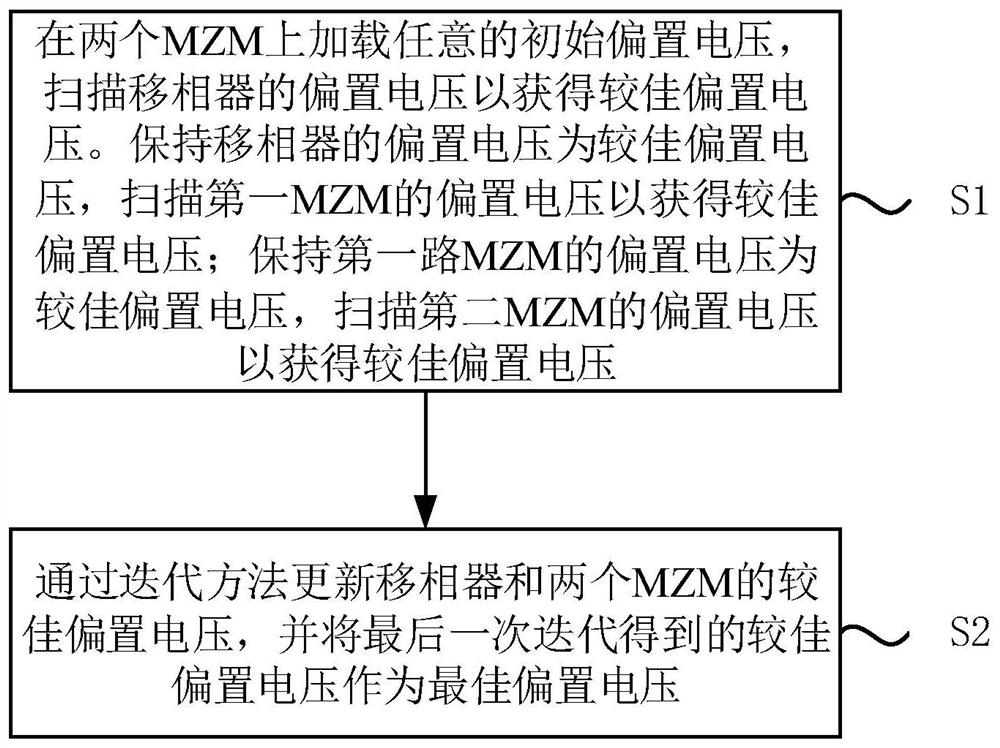
The invention discloses a bias voltage control method and system of an optical IQ modulator, and relates to the technical field of communication. The bias voltage control method comprises the following steps: loading any initial bias voltage on two MZMs, and scanning the bias voltage of a phase shifter to obtain a better bias voltage; keeping the bias voltage of the phase shifter at a better biasvoltage, and scanning the bias voltage of the first MZM to obtain a better bias voltage; keeping the bias voltage of the first MZM as a better bias voltage, and scanning the bias voltage of the secondMZM to obtain a better bias voltage; and updating the better bias voltages of the phase shifter and the two MZMs through adoption of an iteration method, taking the better bias voltage obtained through the last iteration as the optimal bias voltage, and updating the initial bias voltage loaded on each MZM when the better bias voltage of the phase shifter is updated through each iteration. The bias voltage control method and system are high in real-time control precision, stable, reliable and capable of effectively reducing system performance loss.

Description

Technical field [0001] The present invention relates to communication technologies, and particularly relates to a method and system for controlling a bias voltage to an optical IQ modulator. Background technique [0002] Based on the single channel 100 gigabits per second (Gb / s) OTN (Optical Transport Network, OTN) / WDM (Wavelength Division Multiplexing, WDM) optical fiber communication has coherent scale commercial carrier network, the transmission system key technology, for example, polarization multiplexing (polarization Mux, PM), quadrature amplitude modulation (quadrature amplitude modulation, QAM) coherent reception and digital signal processing techniques in a series of core 100Gb / s age widely uniform. With the continued in-depth "broadband China" strategy, operators in provincial, provincial backbone transport networks and metro transport network and other aspects are faced with ever-increasing demand for bandwidth, fiber optic transmission systems need to continuous...

Claims


Application Information

Patent Timeline
IPC IPC(8): G05F1/56H04B10/516H04B10/556
CPCG05F1/56H04B10/516H04B10/5561
Inventor 沈秀娟魏旭立
Owner FENGHUO COMM SCI & TECH CO LTD
Learn More