Electronic device and portable solid state drive

A technology of solid-state drives and electronic devices, applied in the direction of circuit heating devices, electric solid-state devices, semiconductor/solid-state device manufacturing, etc., can solve problems such as discomfort

Pending Publication Date: 2020-11-24
SAMSUNG ELECTRONICS CO LTD
View PDF12 Cites 0 Cited by
  • Summary
  • Abstract
  • Description
  • Claims
  • Application Information

AI Technical Summary

Problems solved by technology

However, when a user uses an electronic product, the user may feel discomfort caused by higher temperature on the surface of the product

Method used


Image

  • Electronic device and portable solid state drive
  • Electronic device and portable solid state drive
  • Electronic device and portable solid state drive

Examples


Embodiment Construction

[0019] Hereinafter, example embodiments will be described in detail with reference to the accompanying drawings.

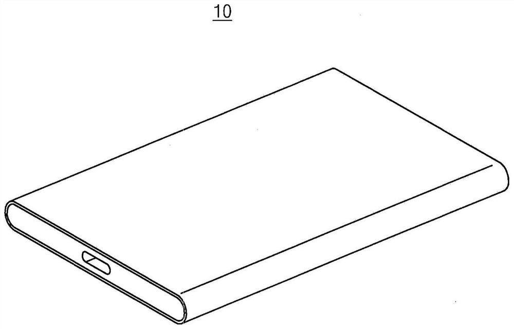
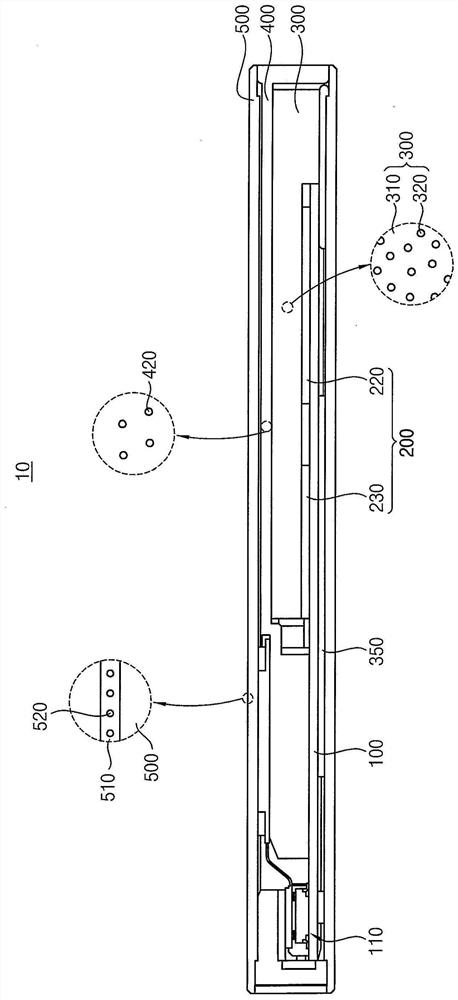
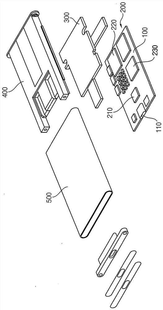
[0020] figure 1 is a perspective view illustrating an electronic device according to example embodiments. figure 2 is showing figure 1 A cross-sectional view of the electronic device in . image 3 is showing figure 1 An exploded perspective view of the electronic device in . Figure 4 is shown set in figure 1 Perspective view of a thermal pad on a stand in an electronic device. Figure 5 to Figure 8 is showing Figure 4 Views of the various structures of the thermal pad in .

[0021] refer to Figure 1 to Figure 8 , the electronic device 10 may include a substrate 100, at least one electronic component 200 mounted on the substrate 100, a heat dissipation pad 300 disposed on the electronic component 200 and in thermal communication with the electronic component 200, and / or cover the substrate 100, the electronic component 200 and the The bracket 400 o...


PUM

PropertyMeasurementUnit
phase transition temperatureaaaaaaaaaa

Abstract

An electronic device and a portable solid state drive are provided. The electronic device includes a substrate; at least one electronic component on the substrate; a heat dissipation pad located on the substrate, in thermal contact with the at least one electronic component, and including an encapsulated phase change material therein; and a bracket covering the substrate, the at least one electronic component and the heat dissipation pad.

Description

[0001] This application claims Korean Patent Application No. 10-2019-0059920 filed with the Korean Intellectual Property Office (KIPO) on May 22, 2019 and Korean Patent Application No. Priority of Korean Patent Application No. 10-2019-0084219, the contents of which are hereby incorporated by reference in their entirety. technical field [0002] Example embodiments relate to an electronic device and a method of manufacturing the electronic device. More particularly, example embodiments relate to an electronic device such as a portable storage device (SSD) and a method of manufacturing the electronic device. Background technique [0003] As electronic products have become miniaturized and functionalized, thermal stability of electronic products is further required. For example, in the case of electronic products such as portable storage devices (SSDs), smartphones, and laptop computers, heat generated from internal electronic components may be dissipated through heat sinks, t...

Claims


Application Information

Patent Timeline
Patent Type & Authority Applications(China)
IPC IPC(8): G11B33/04G11B33/12G11B33/14
CPCG11B33/0411G11B33/121G11B33/1426H01L23/4275H01L23/3737H01L23/3733H01L23/24H01L23/053H01L23/22H01L21/563H01L23/295H05K1/0204H05K1/0209H05K7/20454H01L2224/32245H01L2224/33181H01L2224/2929H01L2224/32225H01L2224/73204H01L2224/73253H01L2224/16225H05K5/0211H01L2924/00H01L23/427H01L24/32H01L25/0655H01L2924/1443H01L21/52H01L24/83H01L21/4871
Inventor 优素福·奇纳尔朴宰弘白善均李韩烘
Owner SAMSUNG ELECTRONICS CO LTD
Why Eureka
Try Eureka