A spliced optical fiber with splice protection, current sensor with such spliced optical fiber and method for protecting a spliced optical fiber

A polarization-maintaining optical fiber and optical fiber technology, applied in polarization optical fiber, cladding optical fiber, and current-only measurement, etc., can solve problems such as short shelf life, and achieve the effect of accurate PER change and simplified protection process.

Pending Publication Date: 2020-11-24
ABB POWER GRIDS SWITZERLAND AG
6 Cites 0 Cited by

AI-Extracted Technical Summary

Problems solved by technology

Disadvantages of this method include sensitive storage and use conditions and relatively short shelf life of the recoating mater...

Abstract

The invention relates to a spliced optical fiber (2) comprising a first and second polarization-maintaining optical fiber (3a, 3b) connected at ends by splicing; to fiber optic current sensors; and toa method for protecting the spliced optical fiber (2) against mechanical stress and/or humidity. A protection tube (7) is arranged around the spliced optical fiber (2) in a splice section (3) of thespliced optical fiber (2). A first (11a) and second end (11b) of the protection tube (7) is sealed to the spliced optical fiber (2) by first and second sealing arrangement (9) for protecting the splice (3).

Application Domain

Optical fibre with polarisationCurrent measurements only +2

Technology Topic

Electrical and Electronics engineeringMaterials science +3

Image

  • A spliced optical fiber with splice protection, current sensor with such spliced optical fiber and method for protecting a spliced optical fiber
  • A spliced optical fiber with splice protection, current sensor with such spliced optical fiber and method for protecting a spliced optical fiber
  • A spliced optical fiber with splice protection, current sensor with such spliced optical fiber and method for protecting a spliced optical fiber

Examples

  • Experimental program(1)

Example Embodiment

[0060] The term "optical fiber splicing" refers to an optical fiber splicing method by using two optical fibers joined obtained. For reasons of simplicity, optical fiber splicing is considered in general terms, and thus may include a protective structure according to the present invention, but depending on the context may refer only to the fact that has been stitching. In particular, it should be emphasized that the term, for purposes of the present invention, prior to application of the protection according to the present invention, splice, the splice whether the processing section of the spliced ​​optical fibers is irrelevant in any way.
[0061] The term "polarization extinction ratio", PER, refers to as the optical fiber is not desired polarization state of the polarization of the light intensity Paul conventionally defined ratio of light intensity of polarization-maintaining fiber in the desired polarization state; that is, the polarization extinction ratio is smaller, desired polarization state in the polarization maintaining fiber (e.g., including defects such as the splice like) stored in the better. Polarization extinction ratio change is defined as the absolute change in the specified temperature range of ambient conditions such as the polarization extinction ratio.
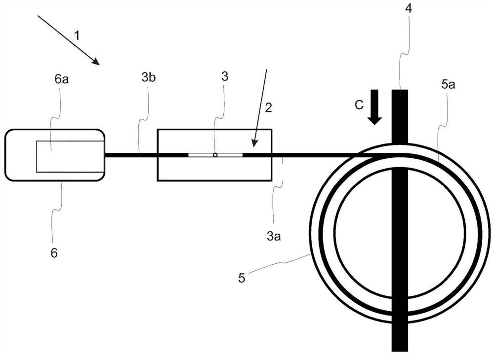
[0062] figure 1 Shows a schematic view of a fiber optic current sensor 1 according to the present invention, which fiber optic current sensor device 1 is C current carried by conductor 4 for measuring the current. Reference numeral 2 and the first polarization maintaining fiber 3a and 3b formed in the second PM fiber splice according to a protected optical fiber according to the present invention having a first polarization maintaining optical fiber 3a and the second polarization maintaining fiber 3b through the one end splicing together. Splice two optical fibers 3 formed 3a, 3b of the joint. On the right side of the figure, a first optical fiber 3a is connected to the other end of the primary converter (PC) 5, and a second optical fiber 3b connected to the secondary converter (SC) 6 at its other end. Secondary converter 6 includes a photoelectric cell 6a, 6a of the photovoltaic cell is optically driven splicing the optical fiber 2, i.e., the photoelectric cell 6a for transmitting light to propagate in the second optical fiber and receiving light from the splicing splicing the optical fiber 2. It will be appreciated that the secondary converter 6 also comprises all other necessary equipment for signal analysis and signal processing, and is connected to a user interface or include known.
[0063] Primary converter 5 includes an optical fiber 5a, 5a is connected to a portion of a first fiber polarization maintaining fiber 3a, and 4 are arranged around the current conductor. Based on the known measurement principle described at the beginning, and are therefore not described in detail.
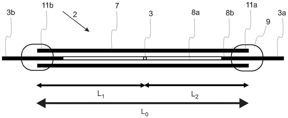
[0064] figure 2 Shows a schematic cross-sectional view of an optical fiber splicing according to the present invention, the protected 2. Protective tube 7 is disposed around the split optical fiber 2, the protective tube 7 at each end portion (here, a first end 11a and a second end portion 11b) connected to the attachment means 9 by a sealing splicing the optical fiber 2. In this figure, the sealing device 9 represented in an exemplary manner, and the binding is image 3 and Figure 4 Placeholder specific embodiments illustrated.
[0065] In one aspect, the protective tube diameter is selected to be larger enough to allow the optical fiber is small difference in length between the spliced ​​optical fibers 7 and the protective tube 2 with moderately curved bend without causing the optical fiber is hardly pressed against the inner wall. On the other hand, the diameter of the protective tube is selected to be small enough so that during the seal may easily be spliced ​​optical fibers 2 remains centered. Preferred protecting tube diameter between 1mm and 25mm, more preferably between 1mm and 5mm.
[0066] In an embodiment, the first PM fiber 3a and 3b in the second PM fiber is inserted before one of the splice protection tube 7, so that the protective tube 7 may be freely displaced along the corresponding PM fiber. After splicing, the protective tube 7 is shifted to its designated position, a position at which the protective tube 7 splice splice enclosure 3 and uncoated section 8a of the optical fiber 2. Alternatively, it is also conceivable to use the protective tube can be clamped onto the optical fiber 2 have been spliced ​​7, as long as the protective tube 7 made of a material suitable for holding and meet the other requirements (for example, thermal expansion of the optical fiber splicing 2 similar coefficient of thermal expansion coefficients) to. In the PM fiber 3a, 3b are respectively connected to the primary transducer and the secondary transducer 5 6 Before the PM optical fiber 3a, 3b for use in splicing, the spliced ​​portion connecting the one end of the optical fiber 2 to 5 or specified converter before 6, the protective tube 7 is inserted on the end portion.
[0067] Another optional step prior to sealing the protective tube 7 around spliced ​​optical fibers 2 may be performed is to apply the hydrophobic substance (e.g., silane solution 3M AP115) on the uncoated fiber splice portion of the segment 2. 8A. Such a process for preventing glass corrosion moisture.
[0068] As it can be seen from the figure, as described above, preferably only applied on the cover seal portion 8b 2 of the optical fiber splice.
[0069] Splice 3 at the respective ends 11b positioned inside the protective tube 7 with the protective tube 7, 11a a distance L 1 And L 2 The total length L 0. exist figure 2 Exemplary embodiment, the distance L 1 And L 2 Preferably equal, but the distance L 1 And L 2 May not be equal, as long as the distance L 1 And L 2 The shortest distance is not less than the minimum length L m To the minimum length L m Determining the derivation in detail below.
[0070] According to a first aspect of the present invention, the length L 7 of the protective tube 0 3 to protect the splice and the respective end of the tube 7 a distance L 11a, 11b of the 1 L 2 It is selected to satisfy the following equation:
[0071]
[0072] Where X 0 Splice is to ensure the maximum polarization extinction ratio is 3, X s Corresponding ends of the protective tube 7 11a, to ensure the maximum polarization extinction ratio at 11b, A (L) is a function of the coherence length of polarization maintaining fiber 3a, 3b, and X m Is the maximum allowable predetermined polarization extinction ratio changes.
[0073] In the case where the splice protection by the protective tube 7 as described herein, mentioned at the beginning of the polarization crosstalk occurs at three different positions. The first position is a splice head 3 itself, wherein polarization crosstalk due to misalignment of the PM fiber axis 3a, 3b during the splicing operation occurs. PER ensure maximum splicing device depends on the use. For mid-range quality stitching machine, in the case of not particularly careful, reaching a value of -30dB is a common, but often difficult to guarantee even careful value of better than -35dB. PER splice in itself stable at all temperatures.
[0074] 3, or the first PM fiber holding spliced ​​optical fibers 3a and 3b in the second polarization-maintaining fiber, the two end portions 7 of the protective tube in the splice 11a, 11b of the polarization crosstalk will occur, wherein the sealing material 2 to the optical fiber splicing cladding portion 8b stress is applied. At low temperatures, with the binder and the hard coating layer, typically increases stress and PER. For applications on a commercial PANDA fiber shrink sleeve bis (binding image 3 and Figure 4 Described), experiments show that, in the temperature range of -25 ℃ to 80 deg.] C, it is contemplated that the maximum PER of -50dB, wherein, at lower temperatures even higher PER. In general the adhesive applied to the test exhibit similar values ​​in the case where the commercial PANDA fiber.
[0075] 7 sealed ends of the protective tube 11a, the maximum PER (light inside the spliced ​​optical fiber 2) of -50dB at 11b (0.002% of the maximum current sensor corresponding to the respective scale factor increases) seems at first sight to be harmless; However, when considering the protected optical fiber splices PER 2, the optical fiber and the protection assembly must be considered as a whole, which must be considered in particular that any interference between the respective positions PER.
[0076] Suppose splice PER 3 is X 0 And the sealed end portions 11a, PER 11b respectively at X 1 X 2 With X 1 Sealed end portion 11b having a X 0 The distance between the splicing position L 1 , And having a splice location X 2 The distance between the sealed end portion 11a is L 2. Consideration of interference, calculation of PER integrally sealed splice protector as follows:
[0077]
[0078] Among them, φ 1,2 = 2πL 1,2 / L B 3 represents the splice and the end of the sealing portion 11a, the difference in polarization between the PM fiber section 11b of the phase shift, L BPM is the fiber beat length, and A (L) is the length L of PM fiber coherence function.
[0079] Physically, the coherence function A (L) is an optical Fourier transform power spectrum; therefore, its width (referred to as the coherence length) is inversely proportional to the spectral bandwidth. For wavelength λ 0 The center has a FWHM bandwidth of Δλ 1/2 Gaussian spectrum, the coherence function is a Gaussian function
[0080] A (L) = exp [- (L / ΔL c ) 2 /2]
[0081] Wherein the coherence length ΔL c = KL b λ 0 / Δλ 1/2 ,and
[0082] For example, a superluminescent diode source having a bandwidth Δλ 35nm FWHM in at 1310nm 1/2. Commercial having PANDA PM1300 3.6mm fiber beat length L B. For this system, the coherence length of the PANDA fiber is ΔL c = 50mm, which means that the degree of coherence in the PANDA fiber in the polarization crosstalk from the 50mm position A (L) down to e -1/2 = 61%.
[0083] For simplicity, assume that L 1 = L 2 = L, φ 1 = Φ 2 And X = φ 1 = X 2 = X s So that the whole can be written PER
[0084]
[0085] For example, take X s ≤-50dB = 0.001%. Thus, X s Temperature changes and the second interference term | 2X s A (2L) cos2φ | <2X s A (2L) <2Xs impact on the overall PER is negligible. In addition, taking into account X 0 Is the only important item constant temperature changes affect the overall PER is In order to reduce the temperature change, the temperature must be within a specified range relative shift of φ = 2πL / L B Changes minimize or suppress interference amplitude
[0086] In the former method, distance 3 may be adjusted splice location between the sealing end portion 11a, 11b with L. Commercial PANDA PM 1300 beat length of the optical fiber temperature coefficient c b = DL b / L b dT is about 6.5 × 10 -4 K -1. In the light source and the fiber parameters given above and where ΔT = 90K (SC temperature range of -25 ℃ to 65 deg.] C), if L = L b / (2c b ΔT) = 31mm, then φ (T) has been reached will change [pi] (corresponding to half the oscillation period of, for example, or a full amplitude varies between minimum and maximum). The L-value for a small portion is impractical, because the optical fiber splicing process requires the release coating layer, which leaves the fiber lengths up to 25mm of the exposed portion 8a on each side. Many also require the sealing material covering the coated optical fiber mm, in order to ensure reliable isolation.
[0087] For the latter method, the only variable is the adjustable L, but in this case, the longer the distance L, the smaller the coherence function A (L). In the background section of the error budget is given as an example, to make a protected splice change scale factor is maintained at 3 ± 0.03% or less, PER variation must be less than ± 0.015%. this means Value X using a worst case 0 And X = -30dB s = -50dB, to achieve the goal, the following conditions apply: A (L) m = 0.375. A light source and fiber parameters given above, which can be drawn from the smallest pitch splice seal portion
[0088] If the splice can guarantee a low PER (e.g., using a reliable PER control routine or high-quality stitching machine), it is possible to reduce the minimum distance L between splice seal portion m.
[0089] To ensure maximum light polarization extinction ratio X splice 0 It depends on the quality and the operating conditions used in the splicer. For mid-range stitching machine, particularly in the case of not careful, reaches a value of -25dB -30dB or are common, and often difficult to guarantee even careful value is better than -35dB. For high-end machines, usually realized value of -40dB. Maximum guaranteed polarization extinction ratio X of the sealed end s Depending on the sealing method or process, and / or the material used and the desired temperature range, because the materials used may shrink and / or hardening at a low temperature. For some double deflating the sleeve, over a wide temperature range may reach a value of -50dB; other sealing materials or processes, e.g., for injection into the tube end portion of the protective binder, or even less than or equal to -40dB the value of -30dB is common. Protected entire splice section the maximum allowable polarization extinction ratio change X m Required by the entire fiber optic current sensor system accuracy, the number of possible scale factor variations, and other components of the system in the system of the splice determined. For example, the current sensor accuracy of 0.2 must be less than ± 0.2%, which includes all of the components influence. The performance of the other components of the splicing section of the system only if a protected, which is the maximum allowable change in the polarization extinction ratio may be 0.015%. If there are two statistically independent protected splice section in the same system, the maximum permissible change in the polarization extinction ratio of each of the spliced ​​section will be 0.011%. For other applications, X m It may be less than or equal to 0.02% or even 0.1%. A typical temperature range is exposed to a splice -40 ℃ to 85 ℃ or temperature range of -20 ℃ to 55 ℃.
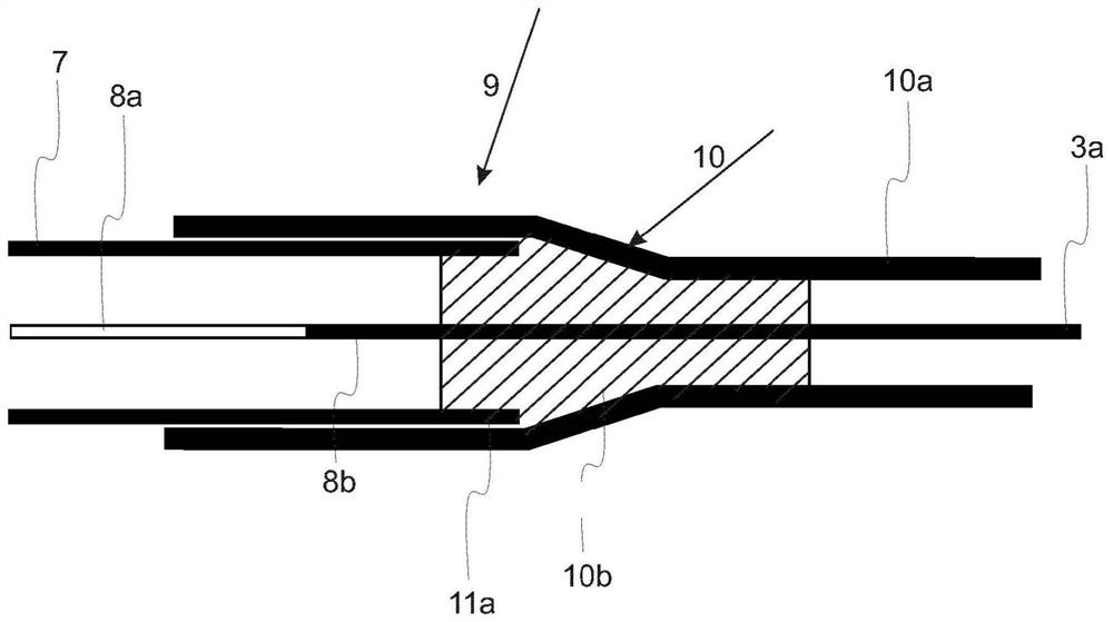
[0090] image 3 and Figure 4 Shows a schematic cross-sectional view of the spliced ​​optical fibers 2 splice protection sealing alternatives according to the present invention. FIG sealing device two ends of the two protective tube 7 shown in a 9 reflects the first alternative embodiment according to the third aspect of the present invention, and Figure 4 The sealing portion is applied to both ends of the protective tube 7 reflects the second alternative embodiment according to the third aspect of the present invention. Not shown in a third alternative (sealed with adhesive). The third alternative involves two end portions 11a, 11b of the adhesive 7 is injected into the protective tube, wherein preferably, wait until the adhesive first end portion 11a of the protective tube is cooled only after fully protective 11b at the second end 7 of the tube the adhesive is injected.
[0091] image 3 Shows a first end portion 11a of the protective tube 7 in a sealed state. A first polarization maintaining optical fiber 3a is shown as having a release coating layer 8a and the holding portion for splicing the coated portion 8b. The first outer sleeve 10 double contraction is shown in a contracted state after the heating, and the first outer sleeve 10 bis shrink outer tube 10a and 10b composed of an inner tube. The inner tube 10b during the application of heat to melt, and the outer tube 10a of the first end portion 11a contracts around the inner pipe 10b and the protective tube 7 to form a seal to protect against moisture and impacts / or mechanical stress. Further, this type of dual deflating the sleeve improves the stability of the PM fiber 3a, 3a PM fiber after the inner cooling tube 10b may be firmly seated.
[0092] Figure 4 Shows a second end portion 11b of the protective tube 7 in a sealed state. A second polarization maintaining fiber 3b is shown as having a release coating layer 8a and the holding portion for splicing the coated portion 8b. The second outer sleeve 12 double contraction is shown in a contracted state after the heating, and the second outer sleeve 12 is contracted by an outer double tubes 12a and 12b composed of an inner tube. The inner tube 12b partially melt during the application of heat, and an outer tube surrounding the inner tube 12a and 12b the protective tube second end portion 11b of the contraction of 7 to form a seal to protect against moisture and impacts / or mechanical stress. Further, this type of dual deflating the sleeve improves the stability of the PM fiber 3b, 3b PM fiber after the inner cooling tube 12b may be firmly seated. As already described, the capillary sleeve 13 is introduced beforehand and fixed to the second outer sleeve 12 of the double internal shrinkage. Deflating the sleeve 14 double splice capillary end facing the sleeve 13 (its left end in the drawing) to seal a second polarization maintaining fiber 3b. As with the contraction of the outer sleeve 12 as double, double shrink sleeve 14 also has an outer tube 14a and the inner tube 14b, similar to the two shrinkage behavior of the tube for the second outer sleeve 12 is explained. Here, a portion of the tube segment 8b covering portion 3b is melted around the PM fiber. Preferably, one or more capillary sleeve 13 is selected to be longer than the inner tube 12b of the second outer sleeve 12 bis shrinkage in the longitudinal direction. Capillary sleeve 13 is advantageously used as a reinforcing element of the PM fiber located at a position of the sealing portion 3b, and also to protect it from direct contact with the inner tube 12b of the PM fiber.
[0093] Preferably, the sealing steps of the method according to the third aspect of the present invention, b) and d) are implemented such that the protective tube is an end portion 11a 7, 11b located in the corresponding first outer sleeve 10 and the second double-shrink outer bis deflating the sleeve of the inner tube 10b 12, 12b and the outer tube 10a, between 12a. Similarly, Figure 4 Alternative sealing step c) is also embodied such that the capillary end of the sleeve 13 is located within the corresponding bis shrink sleeve 14b of the inner tube and the outer tube 14a therebetween.
[0094] Capillary sleeve 13 further has the advantage mentioned at the beginning, as will be described in more detail below. Heat-shrinkable tube usually first radially contracted under heating and then further longitudinal shrinkage upon cooling. In the protective tube at the two end portions 10, 12 are double sealed shrink sleeve 7, this behavior means that the protective tube end portion 11a of 7, PM fiber 3a 11b at, 3b sleeve will shrink during cooling bis tube 10, 12 is pulled into the protective tube 7, thereby causing the optical fibers within the splice protection tube 72, or even slightly curved wound, which potentially increases the stress splicing head. To prevent this problem, in a preferred embodiment, only one end of the protective tube 7 (e.g., a first end portion 11a) using image 3 The second end portion 10 is sealed double deflating the sleeve, the protective tube 7, 11b using inner and outer sleeves 14, 12 and two pairs of shrink sleeve 13 to seal the capillary. The second end portion 11b of the protective tube 7 with a larger double shrink sleeve 12 to the receiving PM capillary seal sleeve 13 of the optical fiber 3b. The inner end (left end in the drawing) of the capillary sleeve 13 using a smaller contraction double sealing sleeve 14 to the PM fiber 3b, the outer end (right end in the figure) is open. In use, a first end of the first portion 11a of the protective tube 7 is heated and sealed. Next, after the first end portion 11a completely cooled, a second end portion 11b of the protective tube 7 is heated. During cooling, the shrinkage smaller inner sleeve 14 and the two larger outer sleeve 12 are contracted in the longitudinal contraction, in which smaller inner sleeve 14 to seal the optical fiber shrinkage into the capillary sleeve 13 ( with the right in the figure), while the larger shrinkage of the outer sleeve 12 into the capillary sleeve 13 in the protective tube 7 (with the left in the drawing). The net effect is largely cancel each other, so that after cooling the sealing portion, the sealing of the optical fiber 2 with respect to the splice protection tube 7 remains at substantially the same position.
[0095]As mentioned, the method steps of the method of the third aspect of the present invention, b) to d) is preferably only performed on the cladding portion of the optical fiber splicing section, so as to reduce the non-coated portion of the optical fiber 2 SPLICING mechanical stress.
[0096] The method of the present invention step a) of the preferred embodiment is substantially the same such that the longitudinal axis of the spliced ​​optical fibers and the longitudinal axis of the protective tube 2 7. In other words, PM optical fibers 3a, 3b preferably in the interior of the protective tube 7 is centered.
[0097] The spliced ​​fiber has many advantages of the present invention. According to the present invention provides an optical fiber splice for splices good protection from mechanical stress and / or moisture. In particular, to reduce the variation due to the difference measures PER according to the present invention is caused by a significant increase such that the fidelity of splicing optical fibers of the polarization state of light transmission, which makes the measurement accuracy FOCS application significantly increased.
[0098] With regard to the method of the present invention, the first alternative because of its good compromise between the quality of the seal, simplicity and cost savings it is preferred. The second alternative is more complicated, but provides better protection at both ends of the tube. The third alternative offers the lowest cost and fastest solution, but at the cost from the point of stress to the optical fiber splicing on a lower quality of the seal.
[0099] Although shown and described presently preferred embodiments of the present invention, it should be clearly understood that the present invention is not limited thereto but may be variously embodied and practiced within the scope of the appended claims. Accordingly, terms such as "preferred" or "special" or "special" or "advantageous" and like terms mean merely exemplary and alternative exemplary embodiments.

PUM

PropertyMeasurementUnit
Diameter1.0 ~ 25.0mm

Description & Claims & Application Information

We can also present the details of the Description, Claims and Application information to help users get a comprehensive understanding of the technical details of the patent, such as background art, summary of invention, brief description of drawings, description of embodiments, and other original content. On the other hand, users can also determine the specific scope of protection of the technology through the list of claims; as well as understand the changes in the life cycle of the technology with the presentation of the patent timeline. Login to view more.
Why Eureka
Try Eureka