Termite detecting, trapping and killing device

A termite and support rod technology, used in hunting equipment, applications, animal husbandry, etc., can solve the problems of hard soil in river dams and difficult to excavate, ant control devices cannot reach the vicinity of ant nests, and black-winged soil termites cannot be trapped and killed.

Active Publication Date: 2020-11-27
上海旭宇信息科技有限公司
View PDF13 Cites 0 Cited by
  • Summary
  • Abstract
  • Description
  • Claims
  • Application Information

AI Technical Summary

Problems solved by technology

[0004] The purpose of the present invention is to provide a termite detection and trapping device to solve the problem that the nesting of termites is generally about half a meter underground, and the nests of black-winged soil termites are deeper. Moreover, black-winged soil termites live on river dams. The ant device cannot effectively trap and kill the black-winged soil termites on the river embankment, and the soil quality of the river embankment is hard and difficult to excavate, so the ant extermination device cannot reach the problem near the ant nest

Method used


Image

  • Termite detecting, trapping and killing device
  • Termite detecting, trapping and killing device
  • Termite detecting, trapping and killing device

Examples


Embodiment 1

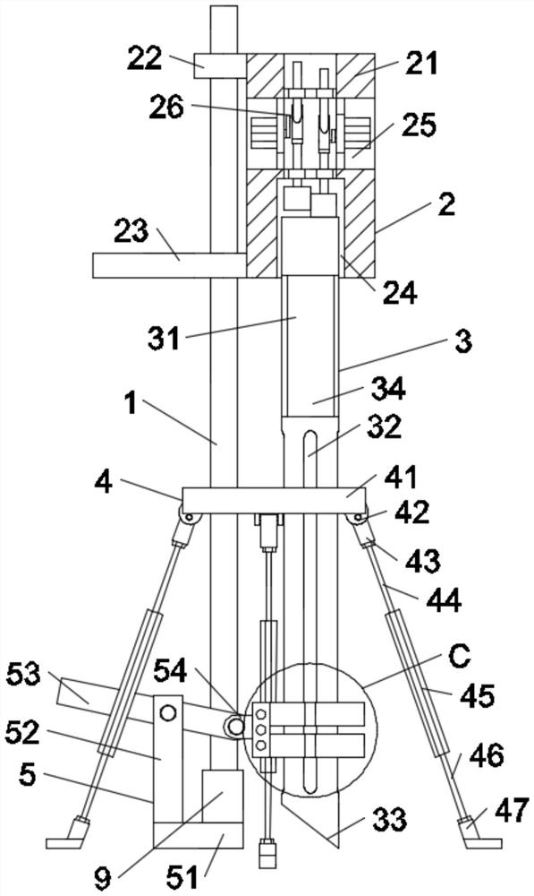
[0025] Such as Figure 1-Figure 7 As shown, in the embodiment of the present invention, a termite detection and trapping device includes a vertical support rod 1, the upper section of the vertical support rod 1 is slidably connected with a knocking device 2, and the knocking device 2 is connected with a casing 3. The middle section of the vertical support rod 1 is slidably connected with a triangular support frame 4, and the bottom end of the vertical support rod 1 is set on the support rod seat 9, and the support rod seat 9 is fixed on the foot-operated pull-out device 5 .

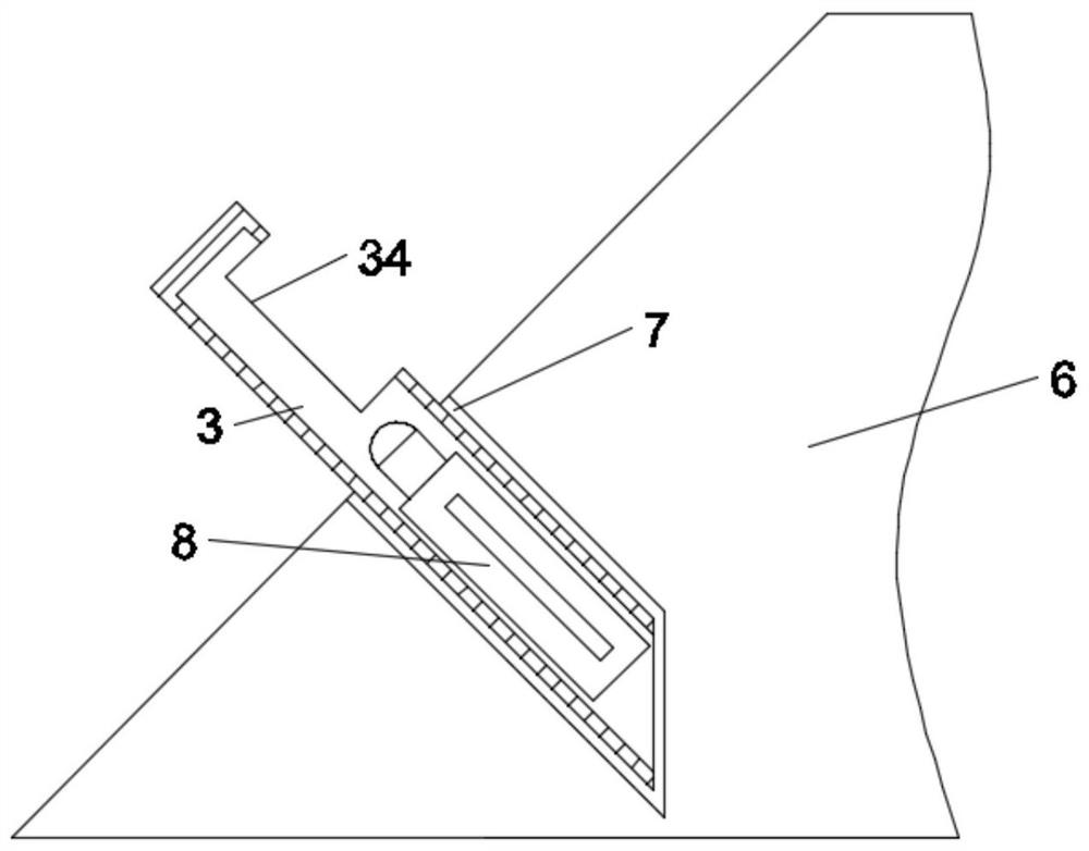
[0026] In the embodiment of the present invention, step 1: the entire device is arranged perpendicular to the slope of the embankment 6, and the triangle support frame 4 is adjusted so as to be stable; Go deep into the slope of the embankment 6 to form oblique deep holes 7; Step 3: step on the foot-operated pull-out device 5, so that the casing 3 is pulled out together with the soil in the pipe, and the ...

Embodiment 2

[0028] Such as Figure 1-Figure 7 As shown, in the embodiment of the present invention, the percussion device 2 includes a housing 21, the upper end of the left side of the housing 21 is fixed with a sliding seat 22 for the vertical support rod 1 to slide, and the left side of the housing 21 The lower end is fixed with a hand-held pressing plate 23, and the inside of the casing 21 is provided with a casing channel 24 for the casing 3 to enter. The casing 21 is provided with an installation space 25, and a knocking mechanism is installed in the installation space 25. Subject 26.

[0029] In the embodiment of the present invention, when the main body 26 of the knocking mechanism moves, the palm presses the hand-held pressing plate 23 , so that the housing 21 moves downward stably, and the housing 21 slides on the vertical support rod 1 .

Embodiment 3

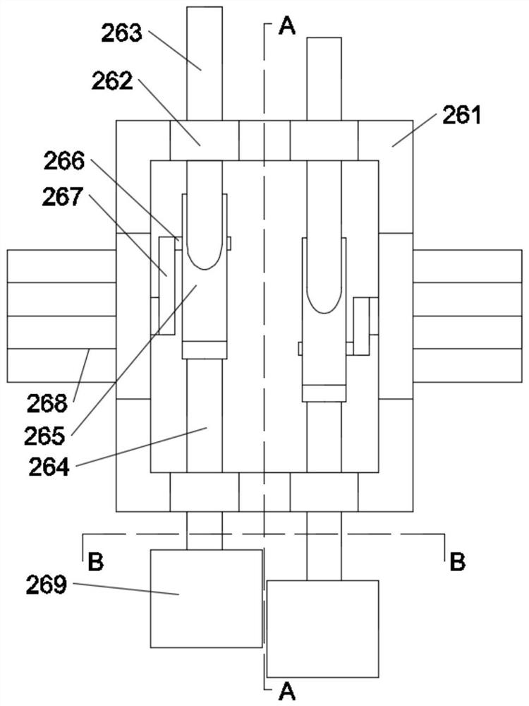
[0031] Such as Figure 1-Figure 7 As shown, in the embodiment of the present invention, the main body 26 of the knocking mechanism includes a back-shaped bottom plate 261, and the back-shaped bottom plate 261 is provided with shaft seats 262 symmetrically up and down, left and right, and the upper and lower two shaft seats 262 are respectively slidably connected. There is an upper sliding shaft 263 and a lower sliding shaft 264, and an oblique connection between the upper sliding shaft 263 and the lower sliding shaft 264 has a return-shaped sloping plate 265 with a rectangular through groove in the middle, and the inner sliding connection of the return-shaped sloping plate 265 There is a cylindrical rod 266 fixedly connected to a rotating plate 267 connected to a motor 268 .

[0032] In the embodiment of the present invention, the principle of movement of the main body 26 of the knocking mechanism: the left and right two motors 268 rotate to drive the rotating plate 267, so th...


PUM


Abstract

The invention relates to the field of termite detecting, trapping and killing equipment, and in particular relates to a termite detecting, trapping and killing device. The termite detecting, trappingand killing device comprises a vertical supporting rod; the upper section of the vertical supporting rod is slidably connected with a knocking device; the knocking device is connected with a sleeve; the middle section of the vertical supporting rod is slidably connected with a triangular supporting frame; the bottom end of the vertical supporting rod is arranged on a supporting rod base in a sleeving mode; and the supporting rod base is fixed to a pedal type pulling-out device. The device can go deep into a river dam, does not damage the dam, cannot reach the vicinity of an ant colony, and caneffectively trap and kill odontotermes formosanus on the river dam.

Description

technical field [0001] The invention relates to the field of termite detection and trapping equipment, in particular to a termite detection and trapping device. Background technique [0002] Termites, also known as worms, are one of the insects that can efficiently degrade lignocellulose in the natural environment. insect. Termites are distributed on 2 / 3 of the earth's land area, most of which are concentrated in tropical and subtropical regions. Among all continents, only Antarctica has not yet found traces of termite activity. Termites can eat a variety of field crops, cash crops, forest trees, fruit trees and seedlings. The damage to river embankments caused by black-winged soil termites is even more serious, and termites cause huge losses to houses, storage materials, and buried plastic cables. [0003] The nests of termites are generally about half a meter underground, and the nests of black-winged soil termites are deeper. Moreover, black-winged soil termites live o...

Claims


Application Information

Patent Timeline
IPC IPC(8): A01M25/00
CPCA01M25/002
Inventor 庞正平魏振兴吕齐洲朱农刘传张露露何海涛
Owner 上海旭宇信息科技有限公司
Why Eureka
Try Eureka